
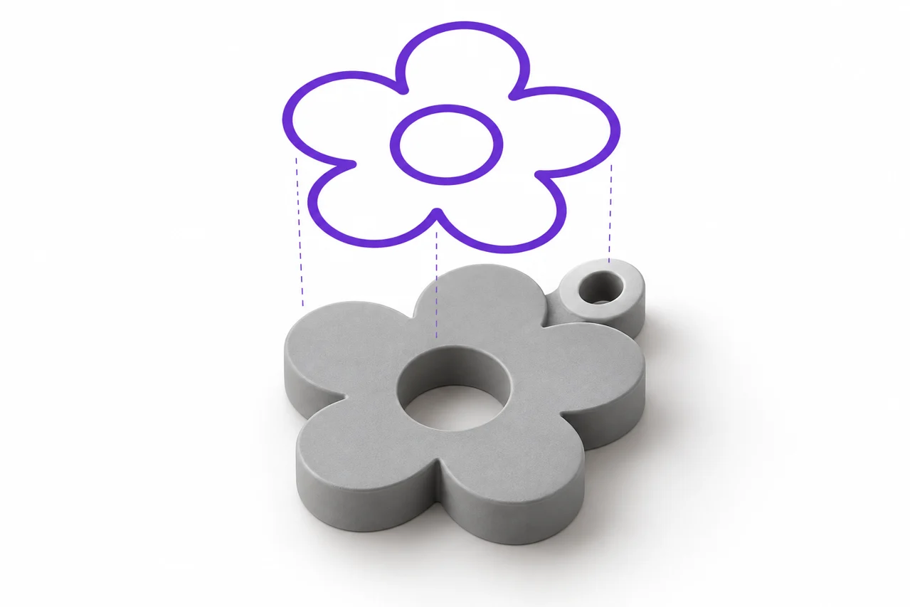
AI-generated editorial illustration, not a screenshot of a conversion result.
SVG to STL is a useful workflow for turning a logo, badge or piece of lettering into a solid extrusion. The cleanest results begin with an SVG that clearly describes the areas you want to print. A drawing can look correct on screen while relying on strokes, font files, clipping or linked resources that a converter does not interpret in the same way. Preparing the artwork deliberately gives you control over the final shape.
Decide what the printed object should contain
Start by separating the visual design from the physical object. A logo may include a symbol, a slogan, a drop shadow and a decorative border. Not all of those elements need to become plastic. Decide whether you want one connected badge, several separate pieces or raised detail on a backing plate. This decision affects how you prepare the paths and whether disconnected regions should be joined before conversion.
For an initial test, use a simple silhouette with a clear outer boundary. Convert it with the SVG to STL tool, inspect the result and then add complexity. If you begin with a file containing masks, effects and many overlapping elements, a failure can be difficult to diagnose. A small successful example establishes that your basic export and extrusion settings are appropriate.
Paths, fills and strokes have different roles
A filled path identifies an area. A stroke describes a line's appearance, including its width and end caps. An open line can therefore look thick on screen without defining a closed filled outline. Before exporting artwork for extrusion, convert important strokes into outlines in your vector editor. This makes the visible line width part of the actual shape rather than a rendering instruction that might be interpreted differently.
Check the result after expanding strokes. Rounded caps can create small protrusions, and overlapping strokes can produce complicated intersections. If several shapes should form one physical region, unite them where appropriate. Do not combine shapes indiscriminately: the interior of a letter such as O is supposed to remain empty, and a Boolean operation applied incorrectly can fill that hole.
Close paths that are intended to enclose material
A tiny gap between path endpoints can be invisible at normal zoom. Depending on how the artwork is interpreted, it may be closed automatically or leave a different boundary than you intended. Inspect endpoints in the vector editor and close the path explicitly. For a filled silhouette, a clear closed outline communicates the design more reliably than a collection of open segments that happen to meet visually.
Convert text to geometry before uploading
Live text depends on a font and its rendering environment. If the font is unavailable or substituted, letter widths and spacing can change. Converting text to paths records the shapes of the letters in the SVG. Keep a separate editable copy with live text, because outlined letters are less convenient to rewrite later.
After outlining, inspect the small details of the typeface. Thin serifs, narrow counters and tiny dots may be unsuitable for the intended print size. A beautiful screen font is not automatically a robust printed object. If you are designing a sign, consider a heavier typeface, a larger size or a backing plate that connects the characters. Our text to STL guide discusses those physical choices in more detail.
Make holes and interior regions unambiguous
Letters and symbols often contain enclosed empty regions. These depend on how compound paths and fill rules describe the design. In a vector editor, toggle a contrasting background behind the artwork and verify that every intended hole is genuinely empty. A white object placed over a black shape is not always equivalent to cutting a hole through that shape, especially when background removal is involved later.
For a simple extrusion, create the intended compound path or subtract the interior region. Then export a fresh SVG and reopen it independently. Reopening is useful because it tests the actual saved file rather than the editor's current document state. If a hole disappears on reopening, fix the vector source before adjusting STL depth or quality settings.
Understand this tool's sampled SVG workflow
STL File Maker decodes supported self-contained SVG artwork into an image and samples that image before building an outline or heightmap. This is not exact conversion of every Bézier curve into a CAD surface. The quality setting controls the number of samples along the longest edge, with 512 samples selected by default. The visible artwork, its proportions and the chosen physical width together determine which details can survive sampling.
That distinction matters for very fine linework. A feature smaller than a sampling cell can disappear or vary with its position. Raising quality can help, but it cannot make every arbitrarily small detail reliable. If exact vector geometry is required for a dimensional part, use a CAD workflow that imports the relevant paths and lets you inspect the resulting sketch before extrusion.
Remove dependencies and unsupported SVG features
The local tool expects self-contained shapes and paths. Linked images, scripts, external resources, live text, use elements and style blocks are rejected by this workflow. Export simple geometry with inline fills. This keeps the conversion predictable and avoids a situation where the design depends on a resource available only on the machine where it was created.
Some editors export a large amount of document metadata or represent repeated elements through references. Look for an option such as plain SVG or an export designed for interchange, then verify the actual result. The goal is not the smallest file at any cost. It is a file in which the visible areas are directly represented by the supported shapes and do not require the original editor to reconstruct them.
Set the viewBox and remove unnecessary canvas space
The viewBox establishes the coordinate region used to display the SVG. It should have valid positive dimensions and include the artwork you want to convert. Excessive empty space around a small logo wastes the available image samples before the foreground is cropped. Fit the drawing area sensibly around the artwork while leaving enough margin to avoid accidental clipping.
Compare the width and height after export. If a circle becomes an ellipse or a square becomes a rectangle, investigate the SVG's dimensions and viewBox rather than stretching the resulting STL by eye. Fixing proportions at the source ensures that future exports remain consistent. When you deliberately need a nonuniform physical scale, make that design choice explicitly and record it.
Choose extrusion settings for the physical object
Outline extrusion gives the selected foreground a uniform depth. It is a suitable starting point for flat badges, tokens and lettering. Heightmap relief instead uses brightness to vary height above a base. A multicolored logo does not automatically need heightmap mode: different colors can produce different brightness values and therefore unexpected steps in the surface.
Choose the final width before evaluating small details. A narrow stem that appears substantial in a 100-millimeter sign may become fragile when the entire design is reduced to 25 millimeters. Depth adds thickness in the extrusion direction, but it does not widen a thin stroke in the artwork plane. Increase the stroke width or change the design when lateral strength is the problem.
Connect islands when you need one piece
Dots above letters, punctuation and separate logo components remain separate solids unless the design connects them. This is not necessarily a conversion error. If you want to handle the finished item as one object, add bridges or a backing plate in the design stage. Place connections where they support the intended appearance instead of relying on accidental overlaps after conversion.
For a keychain, also think about the attachment hole and the material around it. A hole placed extremely close to the edge can weaken the part even when the mesh is closed. Verify the geometry in the slicer at the final size. The number of disconnected outlines reported by a converter is useful information, but it cannot decide how your object should be assembled or used.
Inspect the actual STL, not only the source image
After downloading, open the result in the STL viewer and rotate it to inspect its thickness and boundaries. Check the inside of letters, sharp corners and narrow bridges. Wireframe can help reveal how the sampled outline was triangulated, while a side view makes it easier to distinguish a uniform extrusion from a relief.
Then inspect the sliced layers. A narrow feature that appears in the mesh may still be omitted or altered by the chosen print settings. If the slicer cannot produce the desired stroke, revise the design or printing process. Increasing the mesh's triangle count will not overcome every limitation of extrusion width, material behavior or a fragile layout.
A focused troubleshooting approach
When conversion fails, create a copy containing only one simple shape. If that converts, gradually restore the original elements until the problematic feature becomes apparent. A rejection involving text or linked resources should be resolved in the SVG source. A missing narrow feature suggests that sampling or final physical size deserves attention. A filled interior region suggests that path structure or the chosen background treatment needs review.
Keep the original editable vector document, a simplified SVG export and the downloaded STL as separate files. Those three stages let you make design changes without repeatedly tracing a previous conversion. For artwork that is already a transparent raster image, use the PNG converter and compare the preparation advice in the transparent PNG guide. Choose the workflow that matches the source you actually have.