
AI-generated editorial illustration, not a screenshot of a conversion result.
A grayscale heightmap describes a surface with light and shade. Converting it to STL is straightforward, but producing a useful relief depends on scale, contrast, sampling, and the relationship between the raised surface and its base. Here is a practical workflow for making those choices.
What a heightmap can and cannot describe
A heightmap assigns one height to each horizontal position. It can describe rolling terrain, a decorative relief, or an intentionally painted raised pattern. It cannot describe a surface that folds underneath itself at the same position, such as the underside of a handle. The converter builds the varying top surface, adds side walls, and closes the bottom. The result is a solid relief rather than a complete interpretation of a photographed object. This distinction explains many disappointments that otherwise look like conversion errors.
On the image to STL tool, select heightmap relief when brightness should control depth. Outline extrusion is better when you want one uniform thickness following a logo. The modes share an upload area but answer different design questions. If your main concern is removing the square around a transparent character, start with the transparent PNG guide instead of trying to force a photographic relief into the shape of a clean letter.
Map brightness to height deliberately
Know which end of the scale is raised
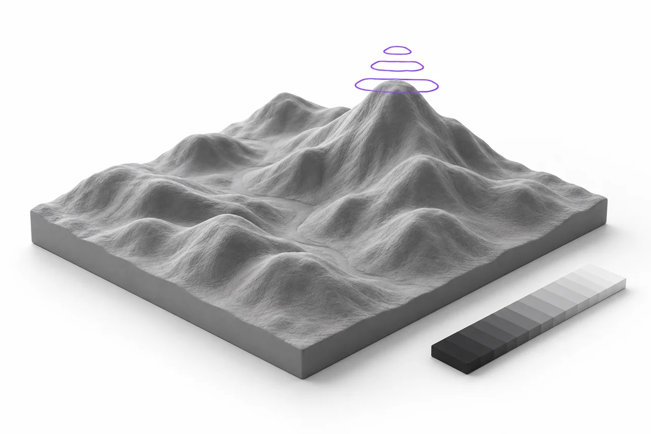
Our default mapping raises dark pixels and keeps light pixels closer to the base. Invert switches that relationship. Neither direction is universally correct: one may suit a black logo on white paper, while the other may suit a conventional terrain image whose highest elevations are white. Before committing to a complex design, try a small gradient with a dark end and a light end. Rotate the resulting preview and confirm that the direction matches your intended surface.
Relief depth is the available vertical variation, not necessarily the final maximum height visible in every model. A picture that contains only midgray tones will use only part of the available range. For example, a nearly uniform image does not suddenly develop full-height peaks merely because you selected a large depth. The base adds thickness beneath this variable surface. Together, the sampled image values, selected depth, and base determine the final bounding height reported by the viewer.
Contrast changes the shape
Increasing contrast pushes more pixels toward the extremes of the height range. That can make shallow details easier to see, but it also creates steeper transitions. Lowering contrast produces gentler changes and may help noisy images. Treat contrast as a geometry decision, not merely a cosmetic photo adjustment. Two images that look equally attractive on screen can produce very different printable surfaces. Save the original and make a separate heightmap version so that you can compare both without losing the source.
Choose a useful source image
Purpose-built grayscale artwork is the most predictable input. It directly expresses which areas should be higher or lower. Ordinary photographs mix several effects: real shape, light direction, reflections, shadows, color, texture, and sometimes compression artifacts. A dark shadow next to a bright highlight can turn into a sharp ridge, even if the photographed object was smooth. The converter follows brightness because that is the information available; it does not know which dark areas represent depth and which represent lighting.
For a photo-inspired relief, reduce distracting backgrounds, soften unwanted texture, and consider painting the height relationships explicitly. Avoid assuming that automatic conversion will recognize a face or separate its subject from the scene. A clean, cropped picture with moderate contrast is a more useful experiment than an entire busy photograph. If the source is JPEG, use the JPG to STL converter; if you need transparent shaped edges, use PNG to STL.
Set physical dimensions before chasing fine detail
Width controls the horizontal size of the detected output in millimeters. Height follows the sampled proportions. Choosing the right physical scale early matters because a feature's printability depends on its real size, not on how large it looks on your monitor. A narrow ridge can be obvious in a zoomed preview and still be too small for a particular printer setup. Compare your intended detail with the line widths and layer heights you actually plan to use in the slicer.
For a first trial, a moderate width and a shallow relief make changes easier to interpret. Keep the depth modest relative to the overall footprint. Increasing depth exaggerates both useful features and unwanted noise. It can also create steep walls where nearby pixels differ strongly. A greater height range does not recover missing information. If an image is blurry, increasing depth usually creates taller blurry geometry. Improve the source first, then choose the amount of depth that suits its visual purpose.
Give the relief a supporting base
The solid base provides continuous material below the varying surface. Our relief mode requires a nonzero base thickness so that the bottom closes even where the heightmap reaches its lowest value. The default is 1 mm. Whether that is sufficient for a physical print depends on footprint, material, handling, and printer settings. A broad flexible plaque and a small rigid token have different needs. Treat the default as an editable starting point and inspect the sliced structure before making a large print.
Choose detail with a sampling budget in mind
The high setting uses 512 samples along the longest image edge. Other dimensions are scaled proportionally. More samples can preserve smaller variations, but they also increase the number of triangles, processing time, memory use, and STL size. A rectangular relief needs both a top and a bottom plus its perimeter walls. Doubling the horizontal and vertical sampling therefore increases the main surface triangle count by roughly four times, not twice. This matters particularly on phones and older laptops.
Use lower detail to explore the overall look, then use high detail for the final export. If the source contains only broad smooth shapes, the additional samples may not visibly improve the result. If it contains many sharp small features, higher detail will reproduce more of them, including defects. File size is not a quality score. A smaller mesh that captures the intended form cleanly can be more useful than a huge mesh containing source noise and imperceptible variations.
Understand smoothing without expecting a repair tool
The smoothing option averages nearby foreground brightness samples before constructing the height surface. It can reduce isolated spikes and soften transitions caused by noise. It does not redesign the silhouette, automatically round every edge, or guarantee a printable model. A strong contrast boundary remains a real change in height even after a local smoothing pass. For important sharp features, compare the smoothed and unsmoothed exports at the same dimensions rather than assuming one is always superior.
When a tiny raised detail disappears under smoothing, there is a tradeoff rather than a mysterious failure. The same operation that removes unwanted fluctuations can also soften wanted ones. Increase that feature's width in the heightmap, reduce noise selectively in an editor, or turn smoothing off. Preserve broad height transitions in the source whenever possible. This usually gives more control than relying on a single global option to distinguish meaningful relief from photographic grain.
Keep a rectangle or preserve a shaped boundary
A fully opaque photograph normally produces a rectangular relief in automatic mode. A PNG with genuine transparency can produce a shaped relief whose boundary follows the opaque foreground. The transparent area does not need to become a solid white plane. You can also choose a full rectangle deliberately when you want a plaque. Background selection and height mapping are separate decisions: one says where material exists, while the other says how high its top surface should be.
Remove-white and remove-black modes select material using image color. They can be useful for simple artwork, but they can also remove similarly colored details inside the subject. If a bright region unexpectedly becomes a hole, examine the background mode before changing depth. For a continuous relief with bright valleys, keep that region as foreground and let the heightmap mapping control its height. The outline preparation guide explains the difference between transparent pixels and opaque white pixels in more detail.
Read the preview as geometry
The model uses a neutral gray viewing material so that shadows help reveal surface shape. Gray does not indicate a particular filament or a color stored in the STL. Rotate to inspect the low side, high side, and underside. Use wireframe to see the triangle structure, but return to the normal shaded view to judge the overall appearance. A preview can make slight relief look dramatic under directional lighting, so also read the reported dimensions rather than judging height only by shadows.
Download the file and reopen it in the STL viewer to inspect the exported geometry. Then load it in a slicer and check several layers. Confirm that the base is present, the footprint fits the intended build area, and narrow features generate actual toolpaths. Mesh generation and printer preparation are different stages. A surface can be mathematically closed yet still contain details that your current material and printer configuration cannot reproduce usefully.
A controlled way to compare settings
Change one variable at a time. Begin with a fixed width, base, and detail level. Export one shallow and one deeper version, then compare them in the same viewer orientation. Next compare smoothing on and off. Finally test inversion if the height direction is uncertain. This approach makes it possible to identify why a model improved. Changing depth, contrast, scale, and background removal together makes it difficult to know which decision created a better or worse result.
Use filenames that record the settings and keep the original heightmap. You can practice with the decorative relief in our free model collection before preparing an original design. If a modeling application needs another mesh format, use STL to OBJ. Our format comparison explains why that conversion preserves triangles but does not restore an editable CAD feature history. A reproducible source-and-settings workflow remains the best way to make substantial changes.
Before calling the relief finished
Check the minimum feature width, total height, base thickness, and intended orientation one last time. Make a small test print when the design is unfamiliar or the detail is critical. A test can reveal whether you need stronger contrast, a wider footprint, or a less aggressive height range. Keep the conversion file and slicer project together so that a successful experiment can be repeated. Thoughtful preparation is more valuable than repeatedly increasing resolution without checking what the physical object needs.