
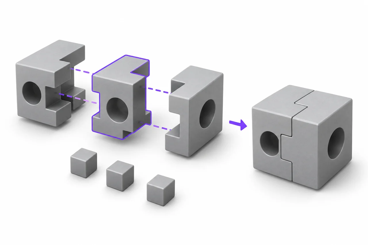
AI-generated editorial illustration, not a screenshot of a conversion result.
Converting 3MF to STL is useful when a printer workflow, older application or recipient needs a plain triangle mesh. The important question is not whether the new file opens. It is whether the exported mesh represents the intended objects at the intended size. A 3MF package can contain information that a standard STL cannot carry, so a reliable conversion includes deliberate choices about geometry, placement and the information you are leaving behind.
Decide whether STL is actually needed
Start by checking the application that will receive the file. If it accepts your original 3MF correctly, converting may offer no practical benefit. Keeping the package can preserve useful context and avoid another interpretation of its contents. If the receiving application specifically requests STL, a conversion is sensible. You might also need a geometry-only copy to inspect a surface independently of a slicer project or to share a single model without distributing your entire project configuration.
Use the 3MF to STL converter for supported core build geometry. Keep the original 3MF alongside the result rather than replacing it. Give the files distinguishable names, such as bracket-original.3mf and bracket-geometry.stl. This makes it possible to return to the source when you later need component definitions or discover that a downstream application interpreted scale differently.
Understand what the package contains
A 3MF file is a package rather than simply a list of triangles. Core model data can describe mesh objects, units, components and a build containing instances of those objects. Additional resources or extensions may describe materials and other features. A slicer can also save application-specific project information. Therefore, two files ending in .3mf can serve different practical purposes even when both contain printable geometry.
That distinction explains why changing the filename extension to .stl does not work. The internal data needs to be read and rewritten. It also explains why a converter that handles a core mesh may reject a project requiring an unsupported extension. A clear rejection is preferable to silently dropping a required part of the model. If you encounter it, open the source in the application that created it and export a simpler geometry package or a direct STL.
Check units before you inspect tiny details
Core 3MF declares a unit for coordinates. Standard STL does not provide a dependable unit field, so the receiving application must interpret numeric coordinates according to its import convention. Our 3MF workflow converts supported declared units into millimeter-sized coordinates. For a part expected to be 40 millimeters wide, the resulting STL should measure approximately 40 units across when imported as millimeters.
Use a dimension that you already know. A hole diameter, overall width or spacing between two mounting points gives you a useful reference. Looking at a model on an automatically fitted preview is not a scale check: a one-millimeter object and a one-meter object can occupy the same area on screen. Read the dimension values and compare them with the source drawing or original application.
Recognize a systematic scale error
If every dimension is wrong by the same factor, investigate units before rebuilding geometry. A factor of 25.4 often points to an inch–millimeter interpretation. A factor of 1,000 can arise between meters and millimeters. Do not repeatedly resize exports until something looks right. Record the source unit, the exported coordinate convention and the receiving application's import setting, then correct the single step responsible for the mismatch.
Preserve components and build placement
A package can reuse an object through multiple component or build instances. Each instance can have a transform that changes its position, orientation or scale. Reading only the first mesh object would miss this structure. A geometry export needs to evaluate the intended build and apply the relevant transforms. Otherwise, an assembly can collapse toward the origin, lose repeated parts or acquire incorrect proportions.
After conversion, count the expected pieces. If a design contains two matching handles and a central bracket, verify that all three are present. Rotate the preview and compare their relative placement. A single STL may contain several disconnected shells; putting multiple components into one file does not make them physically connected. Decide in the slicer whether those shells should stay together, be separated or be printed at different times.
Know which information disappears
Standard STL represents triangle geometry. It does not preserve the full material system, texture images, manufacturing settings or application project history found in richer files. A gray preview is therefore normal for this workflow. It does not mean that the source colors have been converted into gray material inside an otherwise color-aware package. The preview simply uses a neutral display material for the exported surface.
If color separation is central to the print, keep a color-capable workflow. Do not assume that converting a multicolor 3MF to STL will preserve which extruder should print each region. Likewise, support painting, seam preferences and printer profiles should be checked in the original slicing application. For broader comparisons, read our guide to STL, OBJ, 3MF and STEP.
A practical conversion sequence
First, open the original package in its source application and confirm that it represents the version you intend to share. Remove unrelated build items when necessary. Note the important dimensions, the number of intended parts and any information you know STL cannot retain. Save an untouched copy before changing project settings or removing resources.
Next, select the package in the converter and wait for processing to finish. Review any format warning instead of treating it as a temporary inconvenience. If conversion succeeds, rotate the preview and check the displayed bounds. Download the STL using a name that records its purpose or revision. Finally, open that downloaded file in the STL viewer or your receiving application. Checking the actual saved file catches mistakes that an inspection of the source alone cannot reveal.
Separate conversion problems from source problems
A missing feature in the exported STL can have more than one cause. It may be absent from the package's active build, unsupported by the import path, or represented as information that is not ordinary mesh geometry. Compare the original and converted files in a consistent orientation. Identify one specific missing feature rather than describing the entire model as broken. This makes troubleshooting much more productive.
An open edge or self-intersection can also already exist in the source mesh. Conversion does not necessarily repair it. If the same defect appears in both files, change or repair the source geometry and export again. If only the new file has the defect, retain a small reproducible example and note the converter settings. Avoid judging printability solely from smooth shading: visual rendering can hide gaps that matter during slicing.
When the file opens but looks empty
Check whether the package contains printable build items rather than only resources. Then inspect the zoom and coordinate bounds. A tiny object placed far from the origin can be difficult to see in some applications. Try isolating the intended part in the source application and exporting it by itself. If an importer reports unsupported required extensions, switching browsers will not add support for those extensions; export a compatible representation instead.
Inspect sliced layers before using the output
A watertight-looking surface is only one part of a printable workflow. Open the STL in your slicer with the correct unit convention and printer profile. Inspect the first layer, thin walls, overhangs and any interior cavities. Confirm that small parts have not disappeared because they are narrower than the chosen extrusion width or because two surfaces overlap in an ambiguous way.
For an assembly, check clearances between moving components. Those clearances belong to the geometry, while the suitability of a chosen clearance depends on the printer and process. Increasing mesh detail will not create clearance that was never designed. If the issue is mechanical fit, return to the source dimensions. If the issue is faceting on a curved surface, investigate how the mesh was created before the 3MF package was saved.
Manage large packages sensibly
A compressed package can be much larger when expanded. Textures, multiple copies of geometry and application-specific resources can all contribute to processing requirements. The local tool enforces input and expanded-package limits, and a device may run out of practical working memory before a particularly complex scene completes. A smaller geometry-only export can be a better troubleshooting input than an entire production project.
Do not remove resources from the ZIP structure by guesswork. References between package files can become invalid. Instead, use the source application's export options to select the intended objects and omit information that is unnecessary for STL. If a mesh is excessively dense, simplify it in a tool that lets you compare the result against the original shape. File size alone is not a measure of geometric accuracy.
Keep a useful handoff record
When sending the STL to someone else, include the intended units and at least one reference dimension. Mention whether it contains a single object or several disconnected shells, and state that materials or slicer settings are not included. A short note such as “import as millimeters; overall width 40 mm; three separate pieces” prevents more confusion than an unexplained filename ending in final-final.
Retain the original 3MF, the converted STL and the information needed to reproduce the export. If you later need to package a geometry-only STL with explicit millimeter units, see the STL to 3MF guide. That reverse conversion can organize existing geometry, but it cannot restore colors or project information discarded earlier. Choose each conversion for a specific handoff need and verify that need in the receiving application.
How to convert a 3MF file to STL without losing track of the original
Keep an untouched copy of the package and record the intended units, important dimensions and number of build items. Use the converter on a working copy, then inspect the downloaded mesh in the slicer with the same reference dimensions.
An online 3MF to STL converter is useful for a geometry handoff, but it should not replace the original project. Colors, printer profiles and support decisions may still be needed later even when the recipient currently asks only for an STL.
When a .3mf to .stl converter reports an unsupported package
The file may depend on a required extension or an external component that this import path cannot evaluate. Open it in the source application, select the intended object and export a compatible geometry-only package or STL there.
Do not repeatedly rename the file or delete package contents by guesswork. A 3MF document contains structured references; removing a resource can invalidate the package rather than simplify it.
Is there a 3MF to STL converter download?
No separate installer is offered here. Open the browser converter and download the converted STL after checking it. Retain the source 3MF package and its source application when the project depends on extensions or printing settings that the web importer cannot evaluate.
If you need to convert .3mf to OBJ instead, use OBJ in the output selector and inspect the result in a mesh editor. That is another geometry export, not a way to retain the full 3MF project.