
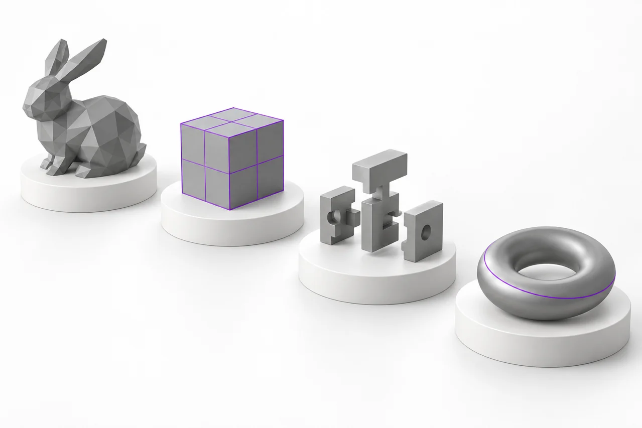
AI-generated editorial illustration, not a screenshot of a conversion result.
STL, OBJ, 3MF, and STEP can all describe three-dimensional work, but they do not preserve the same information. Choosing a conversion starts with understanding whether you need triangles, units, materials, assembly placement, or editable engineering geometry. This guide explains the differences through practical workflows.
Start with geometry, then think about the container
A file extension tells you something about how data is stored, but not whether a particular model is suitable for printing or editing. A mesh represents a surface with vertices and faces. A CAD representation can describe analytic surfaces and their relationships more precisely. Packaging either kind of data in a new file does not automatically repair it, add missing detail, or recreate its original design history. The most useful question is what your next application needs to do with the model.
Our converter directory separates image tools, mesh tools, and CAD import. Images create new geometry from a silhouette or heightmap. Mesh converters translate existing surface geometry. STEP conversion tessellates CAD surfaces into triangles. These are different operations with different losses. If your goal is simply to inspect an STL, use the STL viewer rather than converting it unnecessarily and introducing another intermediate file into the workflow.
STL: a widely supported triangle surface
Standard STL stores triangles through vertex coordinates and normals. It does not reliably encode a unit system, material definitions, textures, object names, or a CAD feature tree. Binary STL is compact relative to its text representation and is a common exchange choice for 3D printing. A gray STL preview is a visualization choice, not a material embedded in the file. Your slicer and printer configuration determine how the geometry is manufactured and which filament or resin is used.
Because the format does not establish a dependable unit convention, import scale deserves attention. Our image-generated files use millimeter-sized coordinates, while STL-to-OBJ conversion preserves existing numeric coordinates. If a file appears 25.4 times too large or too small in another application, an inch-versus-millimeter assumption may be involved. Do not correct this by repeatedly converting the same file. Check the original design size and the receiving application's unit settings, then apply one deliberate scale correction if necessary.
What an STL cannot tell you
A mesh may have gaps, overlapping surfaces, reversed faces, or disconnected shells. The extension alone does not certify that it is a solid. Even a closed surface can contain details that are too small for your printing setup. A viewer helps you inspect the model, and a slicer shows the proposed toolpaths, but neither observation should be replaced by the statement that the file is STL. Treat geometric validity, physical scale, and print suitability as separate checks.
OBJ: flexible polygon geometry with optional companions
OBJ is a text-based format that can describe vertices, polygon faces, normals, and texture coordinates. Material information commonly lives in a companion MTL file, with image textures stored separately. This makes OBJ useful in modeling and visualization workflows, but it also means an OBJ copied by itself may arrive without its appearance. A converter that receives only the mesh cannot reconstruct missing texture images or infer the intended material assignments from the object's shape.
The OBJ to STL converter extracts mesh faces and writes triangles to binary STL. Colors, material references, texture coordinates, and external resources are not transferred. This is appropriate when the next step needs printable geometry rather than the original visual presentation. Check that the source contains faces: a file made only from points or lines does not provide a complete surface for this tool to export. Inspect the resulting STL before continuing to your slicer.
Converting STL back to OBJ
The STL to OBJ tool writes the triangle geometry in OBJ form. It does not reverse the earlier loss of materials or recover smooth CAD surfaces. You may find the result easier to import into a modeling application, but it remains a triangle mesh. The original numeric coordinates are retained. If the importing application interprets those numbers using different units, correct the import configuration rather than assuming that the conversion has guessed your intended scale.
3MF: a package with units and build information
A 3MF file is a package rather than a single plain-text triangle list. Its model description can include explicit units, mesh objects, component relationships, and build placement. Depending on the application and extensions, the package may also contain materials, textures, or manufacturing information. That makes it useful for exchanging richer printing projects, but it also means that translating it to STL can discard information you might still need. Always keep the source package as a separate original.
Our 3MF to STL converter supports core mesh objects, component transforms, and build items. It converts supported source units to millimeter-sized output coordinates and combines the build geometry into an STL surface. It drops colors, materials, textures, and slicer-specific settings. Packages that declare required unsupported extensions are rejected instead of being presented as fully faithful conversions. If that happens, export a core mesh 3MF or a plain STL from the application that created the project.
Placement and multiple parts matter
A 3MF build can place several instances of one object at different positions. Applying the component and build transforms is necessary to preserve that arrangement. Simply reading the first mesh resource would lose the layout. After conversion, inspect the entire bounding box and all expected parts, not only the first visible object. An assembly that was intended for a large build plate may still be too large for your printer even if each component seems small when examined separately.
STEP: CAD exchange before tessellation
STEP commonly carries engineering geometry suited to CAD exchange. Converting it to STL involves approximating surfaces with triangles, a process called tessellation. Flat regions may need relatively few triangles, while curved surfaces need enough segments to represent their shape at the selected tolerance. The output can be convenient for printing or mesh applications, but it no longer contains the same analytic surface representation. Keep the STEP source if future changes may require CAD tools.
The STEP to STL tool uses a browser-loaded OpenCascade import engine and produces millimeter-sized mesh coordinates. It starts with a 0.05 mm linear tessellation tolerance. A smaller tolerance can increase detail and file size; a larger value can reduce processing for large models. This parameter controls surface approximation, not the accuracy of your printer. An extremely fine export cannot overcome mechanical, material, or slicing limitations elsewhere in the workflow.
Why STEP is not the same as editable design history
A STEP import may contain useful CAD surfaces without preserving the exact feature tree from the original design application. Sketch constraints, named operations, and parametric relationships can be absent. Likewise, converting a faceted STL into a STEP container would not automatically create a clean, fully editable solid with the original construction logic. This website does not offer an STL-to-STEP reconstruction tool. Choose an appropriate CAD remodeling workflow when editable design intent is the actual requirement.
Choose the conversion that matches your next step
For a slicer that accepts your current file correctly, conversion may be unnecessary. Keep a 3MF project when you need its printer-specific configuration in the application that created it. Use STL when the receiving workflow wants geometry only and you have checked scale. Use OBJ when a modeling application needs that representation of the mesh. Use STEP as the retained source when CAD surface information matters. The smallest number of deliberate transformations usually makes the workflow easier to verify.
If you are starting from artwork rather than an existing model, use PNG to STL, JPG to STL, or SVG to STL. Those tools create a silhouette extrusion or relief from two-dimensional content. They are not substitutes for CAD file translation. Read the transparent outline tutorial for letters and logos, or the heightmap guide when image brightness should become height.
Use a repeatable verification routine
Before conversion, note the intended dimensions, number of visible parts, and any appearance or assembly information that matters. After conversion, load the result independently and compare those facts. Check a known measurement instead of judging scale by the size of the model on screen. Rotate around the entire surface, inspect holes and thin walls, and look for unexpectedly missing components. If appearance disappeared during a geometry-only export, decide whether that loss is acceptable rather than treating it as a hidden surprise.
Next open the model in the application that will actually use it. For printing, inspect sliced layers and verify the bed fit. For mesh editing, check whether separate parts and face orientation behave as expected. For a CAD-origin model, compare a curved feature against the source to see whether tessellation is visibly coarse. These checks are more informative than comparing only file sizes, because different containers can represent similar geometry with very different storage overhead.
Keep originals and document important choices
Never use the converted file as your only remaining copy of a complex source. Keep the OBJ and its companion textures, the original 3MF project, or the STEP model. Record the conversion route, the units you selected on import, and any tolerance changes. When troubleshooting later, these notes separate an export decision from an application import assumption. Clear filenames also reduce the risk of printing an outdated model after several rounds of conversion and editing.
The free model library provides simple original meshes for practicing downloads and viewer checks. Begin with a small familiar shape before attempting a large assembly. Once you understand what each format preserves, conversion becomes a controlled handoff between applications rather than an attempt to improve a model by changing its extension. The right format is the one that retains the information your next step actually requires.
STL: stereolithography files and units
The name "STL" identifies a triangle-mesh format often used for stereolithography files and other manufacturing workflows. It describes a surface rather than a feature history, and the standard format does not declare real-world units. Confirm a known dimension in the receiving application instead of assuming the extension guarantees millimeters.
3MF file, 3MF format and slicer project: know the difference
A 3MF file is a package that can carry explicit units and build information. A slicer may also save settings or application-specific extensions, so a portable core model and a complete slicer project are not necessarily the same thing. Keep the original 3MF open in its creating application while you compare the exported geometry and dimensions; preserve the .3mf files when project information matters.
Export supported 3MF geometry as STL · Understand core 3MF export
STEP format is CAD exchange, not a renamed mesh
STEP and STP commonly identify CAD exchange files. Turning supported CAD surfaces into STL requires tessellation; the reverse direction requires a separate reconstruction decision. An exported STEP file also does not guarantee recovery of the authoring application’s original feature history.
Tessellate supported STEP or STP geometry · Understand STL to STEP reconstruction