
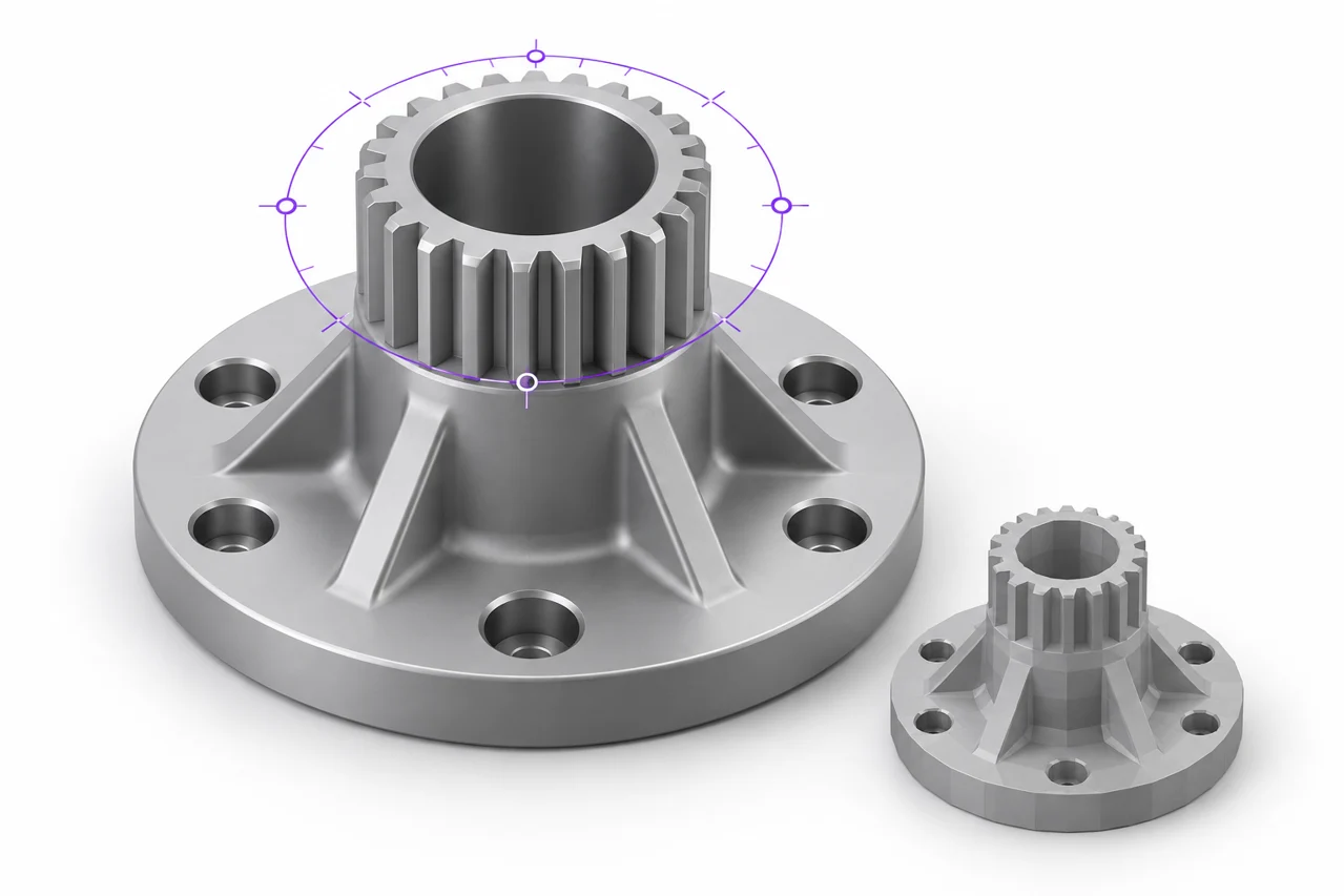
AI-generated editorial illustration, not a screenshot of a conversion result.
An SLDPRT file is a native SolidWorks part document. It can contain design features, sketches, configurations and other application-specific information. An STL contains a tessellated surface. The dependable path from one to the other is to open the part in a compatible SolidWorks environment, choose the intended configuration and export the geometry with appropriate scale and tessellation settings.
If you also need a portable CAD source, export STEP before creating STL. The STEP-to-STL converter can tessellate a supported STEP file in your browser. It does not directly interpret the native SolidWorks feature history. This guide explains how to prepare the source, choose useful export detail and verify the result without confusing a successful file write with a complete manufacturing check.
Open the correct part and configuration
Begin with a compatible version of the authoring application or an authorized workflow that can read the document correctly. Native formats can change between software versions, and a file extension alone does not establish compatibility. If you cannot open the part reliably, ask its author for a STEP or STL export rather than renaming the file.
Select the configuration intended for manufacture. Different configurations can suppress features, alter dimensions or include alternative geometry. The correct-looking filename does not guarantee that the active configuration is the one you need. Compare key measurements and visible features with the drawing or design requirements before exporting.
Rebuild the model and inspect any reported problems. An unresolved reference or failed feature can affect the final body. Do not assume that the viewport's last displayed shape proves that the model is current. Work from a saved, evaluated state that reflects the intended design, and keep a record of the chosen configuration.
Decide which bodies belong in the export
A part document can contain more than one body. Some bodies may be construction aids, alternate forms or components intended for separate manufacturing. Inspect the body list and export scope carefully. Including every visible or available body can produce an STL with unexpected overlapping or disconnected geometry.
If several bodies should form one solid object, consider whether they are actually combined in the design. Visual contact is not the same as a continuous solid. If they are separate manufactured parts, exporting them independently may make placement and process planning clearer. Preserve an assembly reference when relative position matters.
Check hidden and suppressed geometry as well as visible geometry. Export behavior can depend on the chosen command and options. Reopening the output independently is the practical way to confirm what was included. A file that contains the intended body plus an unnoticed reference solid can cause confusion later in the slicer.
Set units and verify a known dimension
The CAD document has a unit context, while STL exchange does not provide a dependable standardized unit declaration. Choose the intended export units and verify the numeric dimensions in the destination. For typical printing workflows, millimeter-sized coordinates are convenient, but the important point is consistency with the importer and manufacturing setup.
Use a known measurement such as overall width, a hole diameter or the distance between mounting centers. Compare it after exporting and importing the STL. A model being automatically fitted into the viewer does not reveal its physical size. Even a major scale mismatch can be hidden by camera framing.
If you export STEP as an intermediate, inspect the result of that handoff too. STEP can communicate units, and the browser CAD workflow uses millimeters for its output. The source document, STEP export and final STL should agree on the intended measurements. Do not add a manual scale factor unless you have identified a specific mismatch.
Choose tessellation based on geometry
Tessellation approximates CAD surfaces with triangles. Finer settings create a closer approximation but can increase file size and processing cost. The useful tolerance depends on the part's curvature, physical dimensions and intended process. A broad flat bracket and a small curved decorative object do not necessarily need the same mesh density.
Inspect curved boundaries where faceting will be visible or dimensionally important. Cylinders, fillets and rounded silhouettes often reveal a coarse export first. Planar faces do not benefit from arbitrary subdivision in the same way. The goal is a sufficiently accurate surface representation, not the maximum possible number of triangles.
Keep numerical settings in context. A tolerance that is tiny relative to the printer's practical capability may produce a heavy file with little useful benefit. Conversely, a coarse setting can visibly alter a small hole or curved mating region. Compare a representative export and measure important features before standardizing the setting for a whole project.
Use STEP when you need an additional CAD checkpoint
STEP is useful when you want to exchange supported CAD geometry before tessellation. Save it alongside the native part when collaboration or a separate conversion workflow requires it. It does not necessarily preserve the complete SolidWorks feature history, but it can carry a more appropriate surface or solid representation than an already tessellated STL.
Upload a supported STEP file to STEP to STL, choose a suitable linear tolerance and inspect the generated mesh. The default is intended as a practical starting point, not a universal manufacturing specification. For unusually complex parts, a coarser trial can help assess the model before requesting a finer mesh.
Read the STEP tessellation guide for more detail about tolerance and surface checks. Retain the STEP source if you may need another tessellation later. Editing a coarse STL cannot reliably recover the exact curved surfaces that a better CAD source already contains.
Inspect thin features and internal geometry
Small ribs, narrow walls and shallow engravings can be valid CAD features while still being difficult to manufacture with the chosen process. Exporting them successfully does not establish that they will survive slicing or printing. Check their physical size and inspect how the slicer represents them in the layer preview.
Internal cavities deserve separate attention. A closed outer surface can contain channels or voids that require particular support or cleaning access. Confirm that the exported mesh preserves those regions and that the intended process can produce them. A shaded external view cannot show every internal feature.
For a functional part, distinguish geometric clearance from process allowance. The CAD model may define nominal dimensions, while the printed result depends on material, orientation and calibration. Use representative test pieces when fit matters. Do not compensate for an unknown manufacturing issue by repeatedly changing the export scale without understanding the cause.
Verify the STL outside the source application
Open the STL in the STL viewer and compare it with the source. Check overall dimensions, curved silhouettes, openings and body count. Rotate the model to inspect the underside and any regions that were hidden in the original working view. Wireframe can help reveal whether the tessellation is unexpectedly coarse or dense.
Then import it into the destination slicer and inspect layers. Look for missing thin features, unintended solid regions, detached components and unusual first-layer placement. The slicer's interpretation is part of the actual manufacturing workflow, so it deserves its own check even when the mesh appears correct in a general viewer.
If you discover a design problem, return to the native part where possible. A parametric change is usually easier to document and reproduce than a manual edit of a dense triangle mesh. The STL editing guide explains when mesh edits are useful and when reconstruction or source-level changes are more appropriate.
Keep a clear record of the exported revision
Save the native part, selected configuration, portable CAD export and final mesh with consistent revision identifiers. This prevents an old STL from being mistaken for the latest design. If the change affects fit or manufacturing, include a short description of the altered feature and the measurement that confirms it.
When sharing only STL, explain that the file is a mesh and does not include editable sketches or feature history. When sharing STEP as well, identify which file was used to generate the mesh. A recipient can then retessellate the correct revision if their process requires a different level of detail.
For repeatable exports, record the unit choice and tessellation settings in the project notes. These details are especially useful when several people generate manufacturing files from the same family of parts. A measured check on a known feature remains necessary, but a documented setup reduces avoidable variation between exports.
Test the critical interface first
If a large part contains one important snap, hole or mounting surface, consider producing a small test section at the final scale. Use the intended material and orientation so the result reflects the actual process. This can reveal fit issues before a full print, while the preserved CAD source makes it straightforward to adjust the relevant feature and regenerate the mesh.
The most reliable SLDPRT-to-STL workflow keeps design preparation, tessellation and manufacturing checks distinct. Open the correct configuration, select the intended bodies, verify units, choose useful detail and inspect the output independently. That process produces a mesh whose origin and limitations are clear, while retaining the native document needed for future changes.
What is SLDPRT?
An SLDPRT file is a native SolidWorks part document. It can retain editable modeling information that a triangle-only STL export cannot preserve. Keep the part document as the design source and export a separate STL for the downstream mesh workflow.
SolidWorks STL export: parts and assemblies
A part export and an assembly export are not the same task. An assembly can reference multiple component documents and configurations, so verify which resolved components and placements are being exported. Exporting an SLDASM assembly to STL therefore requires an assembly-aware workflow, not just a renamed part file.
Select the STL format SolidWorks offers for mesh exchange, then set the units deliberately and inspect tessellation on curved surfaces. Keep the original SLDPRT beside the STL SolidWorks exports so design revisions remain traceable to the source part. No direct SLDASM or SLDPRT importer is available here. If a STEP export is appropriate, preserve a known dimension and review the imported geometry before generating the mesh.
Convert supported STEP or STP geometry · Inspect the exported STL
Check the SLDPRT filename before import
SOLIDWORKS native part files use the extension .sldprt. If your filename ends in .sdlprt, the letters are in a different order. Confirm the actual format with its author and request a verified SLDPRT or STEP export. Renaming an unrelated file does not turn it into a SOLIDWORKS part.