
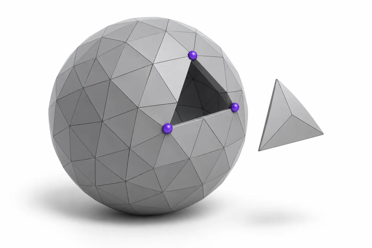
AI-generated editorial illustration, not a screenshot of a conversion result.
Editing an STL means working with a surface made of triangles. The file does not normally contain named sketches, extrusion features, dimensional constraints or the construction history of the original design. That does not make it uneditable. It means you need to choose a method that matches the change: mesh operations for surface edits, or reconstruction when you need a dimension-driven CAD model.
Begin by deciding what success looks like. Rotating a decorative object, cutting a flat base, enlarging a hole and redesigning a mechanical assembly are different tasks. A suitable workflow for one can be inefficient or inaccurate for another. Use the STL viewer to inspect the file, then follow the steps below to plan the edit, preserve a reference and verify the result.
Inspect the file before choosing an editor
Check the overall dimensions, orientation and number of disconnected parts. A file can contain several shells even when the shaded view resembles one object. Some shells are intentional, such as separate letters or assembly components. Others are fragments left by scanning or previous repairs. Understanding the structure avoids accidentally deleting useful geometry or merging parts that should remain independent.
Look closely at the regions you intend to change. A low-resolution circle may already be visibly faceted, while a scanned surface may contain dense uneven triangles. Those sources respond differently to editing. Increasing triangle count later does not automatically recover the missing curvature of a coarse export, and reducing a scan too aggressively can erase the detail you wanted to preserve.
Confirm the intended units using a known measurement. STL coordinates do not carry a dependable universal unit declaration. If you plan to enlarge a 5 mm hole, first make sure the whole model is being interpreted at the correct scale. Write down the reference measurement and keep it available throughout export and reimport.
Keep the original and work on a copy
Save an untouched copy before applying repair, simplification or Boolean operations. Some edits are destructive in the practical sense that they discard geometry that is difficult to recover. A repair tool may fill a hole you intended to keep, or merge nearby surfaces that belong to separate parts. An original reference lets you compare the change instead of relying on memory.
Use clear revision names and record what changed. For example, distinguish a version with only a flat base from another with a larger mounting hole. If several operations are needed, save checkpoints between them. This makes it easier to locate the operation that introduced a problem and to retry only that step.
Preserve the working application's project format as well as exported STL files. A project can keep selections, modifiers or separate objects that disappear during export. The exported mesh is useful for exchange, but it may not contain the editable structure you used to create the modification. Keeping both reduces unnecessary repeated work.
Use mesh operations for straightforward shape edits
Moving, rotating and uniformly scaling an object are usually direct mesh tasks. A planar cut is another common example: you can remove a region below a chosen plane and close the resulting boundary. These changes do not require reconstructing every triangle as an analytic CAD surface. A mesh editor can work directly with the existing representation.
For a cut, inspect the cap and adjacent surfaces after the operation. A plane through several overlapping shells can produce multiple boundaries, and a tool may handle them differently. Confirm that the new base is actually flat and closed. In a slicer, examine its first layers rather than assuming a smooth-looking cap is valid.
Uniform scaling changes all dimensions together. Nonuniform scaling can distort circles into ellipses and alter relationships between mating features. If you only need a larger hole, stretching the entire model is usually the wrong operation. Define the local change instead, using a suitable cutter or rebuilding the relevant feature.
Use Boolean operations with clean intersections
A Boolean difference can create a hole by subtracting one volume from another. A union can combine a backing plate with raised lettering. These operations work most predictably when the participating meshes are closed, consistently oriented and clearly intersecting. Surfaces that barely touch or occupy exactly the same plane can create ambiguous geometry.
Position the cutting object using measurements rather than only a perspective view. For a mounting hole, check its center, diameter and direction. Extend the cutter fully through the intended region so that no thin cap remains. After applying the operation, inspect both entrances and any internal wall created by the cut.
A visual overlap is not necessarily a merged solid. Two objects can appear joined while remaining intersecting shells. If the downstream process requires one continuous volume, use an actual union and check the result. This distinction is especially relevant for text and logos, where a backing can visually connect islands without a successful geometric merge.
Repair defects without erasing intentional openings
Common mesh defects include open boundaries, inverted faces, duplicate surfaces and self-intersections. Repair tools can help identify and correct these problems, but a one-click repair is not a guarantee that the intended design survives. The tool cannot always distinguish a missing face from a deliberately open mouth or channel.
Inspect each repaired region against the original. If a large opening was filled, ask whether it was supposed to be closed. If several components were combined, check whether their separation was functional. On a scan, automatic cleanup may smooth away shallow engraving or small edge details that looked like noise to the algorithm.
Use the slicer's layer preview as an additional check, not the only one. Some slicers compensate for certain mesh defects during slicing, which can hide problems that remain in the exported file. A model that prints acceptably in one application may still behave differently in another. Save a clean geometry result whenever the edited file will be shared.
Choose CAD reconstruction for dimension-driven changes
If you need to change a precisely located feature repeatedly, rebuild the relevant geometry in CAD. Use the STL as a visual or measurement reference, then define sketches, dimensions and features that express the new design intent. This can be more work initially, but it produces a model whose important dimensions are easier to control.
A direct mesh-to-solid conversion does not necessarily create a clean parametric model. It may represent every triangle as a separate planar face. Such a result can be large and awkward to edit, especially when the source mesh is dense. The file format may change while the underlying faceted structure remains.
Our STL-to-STEP guide explains this distinction. STEP can contain CAD geometry, but exporting a faceted representation to STEP does not recover the original sketches or smooth surfaces automatically. Decide whether you need a temporary solid for a limited operation or a properly reconstructed model for future design work.
Simplify only when the edit benefits from it
Decimation reduces the number of triangles. It can improve responsiveness and make a heavy scan easier to manipulate, but it changes the surface approximation. Choose a reduction based on visible and dimensional error, not a target file size alone. A flat region may tolerate substantial simplification while a small curved feature does not.
Protect important boundaries where the application allows it. Holes, sharp edges, mating surfaces and thin walls deserve close comparison. After simplifying, measure the features that matter and view the silhouette from several directions. A model can look similar from one angle while losing a critical notch on the opposite side.
Subdivision has the opposite numerical effect but does not inherently add trustworthy detail. Splitting triangles creates more vertices; smoothing those vertices changes the shape according to an algorithm. Neither operation knows the exact original CAD surface. Use these tools intentionally for appearance or editing convenience, not as a promise to recover absent accuracy.
Export and reimport the edited result
After editing, export a new STL and open it independently. Check scale, orientation and the modified areas. This catches mistakes in object selection, transform application or export scope. If the working scene contained cutters, reference objects or hidden copies, confirm that they did not accidentally become part of the output.
For an editor that prefers OBJ, the STL-to-OBJ tool preserves the triangle geometry in a different representation. Read the STL-to-OBJ workflow guide before assuming it adds materials or editing history. When the work is finished, OBJ to STL can return supported polygon geometry to a printing-oriented mesh format.
Finally, compare the result against your original definition of success. The new base should be flat, the hole should have the intended size, and surrounding geometry should remain intact. Slice a representative result and review the layers before manufacturing. Effective STL editing is not about using the most complicated operation; it is about making the smallest well-understood change and verifying that the exported mesh actually contains it.
Test fit with a small section when possible
For a large part with one critical connection, consider printing a small section that contains the modified interface. This can reveal clearance problems without consuming the material needed for a complete prototype. Keep the section at the final scale and use the intended orientation and process settings. A successful local fit does not validate every part of the full design, but it provides useful evidence about the specific feature you changed.
Choose an STL editor for the change you need
To edit STL files, first decide whether you need to move mesh vertices, cut or combine surfaces, repair defects or rebuild editable CAD features. A format conversion alone is not a full editing operation. Keep a copy of the original and compare both shape and dimensions after the edit.
If you only need inspection, use the viewer without changing the geometry. This site provides conversion and viewing tools; the guide explains editing choices rather than offering a full browser-based STL editor.
Inspect an STL without editing it · Understand mesh-to-CAD reconstruction