
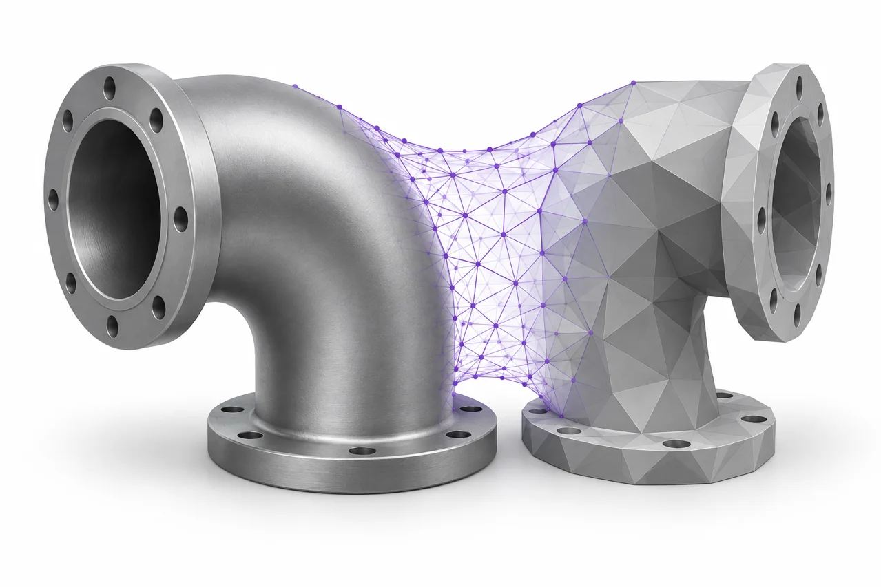
AI-generated editorial illustration, not a screenshot of a conversion result.
STEP to STL conversion turns CAD geometry into a triangle surface. The task is straightforward when you know the desired size and the detail that matters, but a poor export can produce visibly faceted curves, unnecessarily large files or surprising scale changes. This guide explains how to choose tessellation settings, inspect the result and distinguish a mesh approximation from the original CAD model.
Understand what changes during conversion
A STEP file can describe CAD surfaces and their relationships in a way that is different from a triangle mesh. A cylinder may be represented through analytic geometry rather than a ring made from a fixed number of straight sides. STL requires triangles. During conversion, a tessellation engine approximates the CAD surfaces with planar facets. More triangles can follow curvature more closely, but they also increase processing and file size.
The resulting STL does not keep the original design history, sketches, constraints or editable feature tree. Even when the surface approximation is excellent, the file remains a mesh. Keep the STEP source if you expect to change a hole diameter, adjust a fillet or send the part to another CAD workflow. Use the STEP to STL converter when your next application needs tessellated geometry.
Start with the dimensions that matter
Before changing quality settings, write down one or two reference dimensions. Overall length is useful for checking scale, while a bore diameter or mounting-hole spacing is useful for checking a functional feature. A preview usually fits the object to the available screen area, which makes a large and small object appear equally prominent. Dimension readings provide evidence that visual size cannot.
Our STEP import requests millimeter-sized output coordinates. Standard STL does not reliably declare units, so import the result as millimeters in the receiving application. If that application uses a different convention, change the import interpretation deliberately. A uniform size error is usually a unit issue; adding triangles or reducing tessellation tolerance will not correct it.
What linear tolerance means
Linear tolerance, often discussed as deflection or chordal deviation, controls an aspect of how closely the faceted approximation follows a curved surface. A smaller value generally asks the tessellator for a closer approximation. In this tool, the default linear deflection is 0.05 millimeters. That is a starting point, not a universal guarantee that every exported coordinate is within a stated manufacturing tolerance of every source surface.
Consider the intended use. A large decorative shape may look smooth enough with a coarser mesh, while a small curved feature can benefit from finer tessellation. A very small tolerance can dramatically increase triangle count without delivering a visible or useful improvement in the next step. Choose the setting by comparing results at the final scale rather than by assuming the smallest number is always best.
Do not confuse tessellation with print resolution
Mesh detail and printing resolution are related but different. Layer height affects the printer's vertical stepping. Nozzle diameter, extrusion width and motion control affect other parts of the printed result. Tessellation controls the input surface approximation. A dense STL cannot eliminate layer lines, and a fine layer height cannot turn a twelve-sided mesh into a mathematically exact cylinder.
Angular detail also matters
Tessellation engines can use angular constraints alongside linear ones. The local STEP tool uses an angular deflection setting of 0.1 radians. This participates in the engine's surface sampling and is not a user-facing promise about the finish of a physical print. Two CAD models with different curvature and topology can produce very different triangle counts under the same settings.
When reviewing a circular feature, inspect its silhouette as well as its shaded surface. Smooth lighting can hide flat facets, while wireframe makes triangle structure obvious. A change that increases triangles only on already flat regions may not improve the feature you care about. Compare a moderate and fine export, then choose the smaller file when both satisfy the intended visual and dimensional checks.
A reliable first conversion
Open the STEP source in a CAD application if you have one and confirm that it contains the correct revision. Check whether the export includes one solid, several bodies or an assembly. Remove unrelated parts through the source application rather than expecting the converter to guess which component is important. Save a separate simplified handoff file when the original assembly contains many components that will not be printed.
Upload the STEP or STP file and begin with the default fine setting. The CAD engine loads in the browser, so its first use can take longer than a simple image conversion. When processing finishes, check orientation and bounds, then inspect small curved features. Download the result and reopen the saved STL. Keep the settings and source revision together so you can reproduce the result later.
Compare quality settings with a controlled test
If you are unsure whether finer detail is useful, change only the tessellation setting. Convert the same source twice, give each result a descriptive filename, and compare triangle counts and silhouettes. Look especially at holes, fillets, rounded outer edges and shallow curves. Changing source geometry, scale and tolerance simultaneously makes it difficult to identify the cause of an improvement or failure.
For a functional part, review the geometry at its intended physical size. Zooming until individual triangles fill the screen is useful for understanding the mesh but can exaggerate imperfections that have no practical effect. Conversely, fitting a tiny bore into a large assembly view can conceal a problem. Inspect important features individually and keep the purpose of the part in mind.
Assemblies and disconnected bodies
A single STEP file may contain multiple bodies. An STL export can place their triangles in one file without combining them into a single solid. If two bodies overlap, the export does not automatically perform a Boolean union. If they are separated, the STL can contain multiple disconnected shells. Those outcomes may be correct, but they should be deliberate.
Count the parts in the preview and check their relative placement. If you need separate STL files, exporting individual bodies from the source application is often clearer than trying to separate a combined mesh afterward. If you need one printable solid, perform the appropriate solid-modeling operation before tessellation and verify that internal faces or overlapping regions have been resolved.
When a feature appears to be missing
First determine whether the feature is geometric. Color, surface appearance and named construction objects are not necessarily part of the physical boundary that becomes an STL. A hole that is actually modeled should affect the surface, while a painted mark will not become an engraved detail merely because the file is converted. To print a logo as relief, model or extrude it as geometry before export.
If genuine geometry disappears, compare the STEP file in another CAD viewer and isolate the affected body. Very small faces, invalid topology or an unsupported representation may complicate import. Try a fresh export from the source application. Record the exact missing feature, source dimensions and export settings. This provides a useful diagnostic case without requiring someone else to infer the intended design from an entire complex assembly.
Open surfaces and solid expectations
Not every CAD file describes a closed solid. A surface model can tessellate successfully and still have open boundaries. That is appropriate for some visualization workflows but often unsuitable for ordinary solid printing. A successful conversion message means that geometry was produced; it does not certify that the source was a valid closed volume.
Inspect the downloaded mesh in your slicer and look through the layer preview. Unexpected gaps, missing walls or an empty interior can reveal an issue that is not obvious in a shaded viewer. Repairing a small mesh defect can help, but if the source was intentionally an open surface, the correct solution may be to thicken or close it in CAD. Guessing a cap in a mesh editor can change the intended form.
Handle large models without sacrificing the wrong detail
Large assemblies and highly detailed curved surfaces can consume substantial browser memory. The tool has input, processing-time and output-triangle limits. A limit message is a reason to simplify the task, not an instruction to keep clicking Convert. Isolate the required bodies, remove irrelevant components and try a less demanding tolerance when appropriate.
Preserve important interfaces while simplifying. A decorative screw thread may be unnecessary for a presentation model, whereas a locating pin or sealing surface could be central to the part's function. Simplification decisions are easier to make in the original CAD environment where the design intent is visible. Reducing a completed mesh indiscriminately can remove exactly the detail you were trying to retain.
Check the exported file in its real destination
Use the STL viewer for a quick rotation and dimension check, then continue into the application that will actually use the file. A slicer review should include the intended orientation, scale, thin walls and support requirements. A mesh-editing workflow should confirm that the expected shells are present and that no transform was applied twice.
When sharing the export, state its coordinate units and the tolerance used. Keep the original STEP available for anyone who needs CAD geometry rather than triangles. If the next request is to turn the mesh back into a CAD file, read the STL to STEP guide first: wrapping facets in a CAD container does not recover the original cylinders, sketches or design history. A careful forward conversion preserves a useful surface while keeping those limits clear.
How to convert a STEP file to STL before changing quality settings
Start with the correct revision and isolate the bodies you intend to export. If you need to convert STEP files to STL from an assembly, decide first whether the recipient wants all bodies in one file or separate exports. The browser tool processes one input at a time; it does not provide a batch conversion queue.
For a .stp file to STL handoff, record the same reference dimensions you would for a .step source. Filename spelling does not change the geometry checks, tessellation choices or unit interpretation.
How to convert STP to STL with the same geometry checks
The .stp and .step filename extensions refer to the same STEP exchange format. An STP to STL converter follows the same essential process: read the CAD model, tessellate its surfaces and write the triangles. Choose the input file by its actual contents rather than changing the extension to make an unsupported file appear compatible.
When converting STP to STL, record one overall measurement and one important feature before export. Compare both after import into the slicer. If the dimensions change by a uniform factor, resolve the unit interpretation before trying a finer tolerance.
A STEP to STL converter Mac users can try in a browser
Use the web tool to convert a STEP file to STL online when the supported geometry fits the browser limits and you need a straightforward handoff. The same workflow can convert STEP to STL online on a supported Mac browser. A desktop CAD application can be the better place to isolate bodies, repair surfaces or control assembly exports before tessellation.
There is no separate STP to STL converter download for this website. The page loads the CAD engine and processes the model on your device. If you use an STP to STL converter online, keep the source model and settings alongside the result so the export can be reproduced.
Choose STEP to OBJ or STEP to 3MF when STL is not the right handoff
The output selector also offers STEP to OBJ geometry export. Choose OBJ when the receiving mesh editor needs vertices and faces in that format. The CAD surfaces are still tessellated; changing the mesh container does not preserve analytic curves or design history.
You can also convert STEP to 3MF by choosing 3MF as the output. This packages the tessellated geometry rather than the original CAD model or a complete slicer project. Verify the model scale and placement in the receiving application, whatever output you choose.
How to convert .step to .stl without confusing filenames
A file named bracket.step and one named bracket.stp can both contain STEP data. Whether you use a .step to STL converter or a .stp to STL converter, confirm the actual source format and keep an untouched original. To convert .step to STL, select the source file and let the importer read the geometry; changing its filename to bracket.stl cannot create triangles.
The same warning applies to an STP file to STL handoff. If a recipient asks how to convert a STEP file to STL, provide the converted mesh and its intended units, rather than a renamed CAD document. Keep the source available for later CAD edits.