
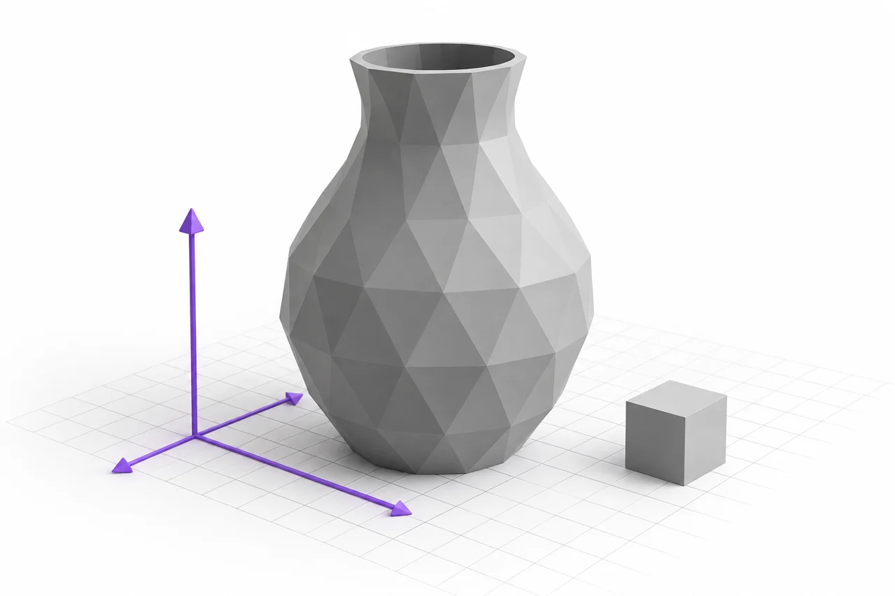
AI-generated editorial illustration, not a screenshot of a conversion result.
A Blender scene can contain far more than the physical surface you intend to export. Objects, modifiers, linked data, materials, animations and scene settings all contribute to what appears in the viewport. Preparing an STL means choosing a specific evaluated mesh, arranging its dimensions and exporting only the intended geometry. The final file will not preserve the full scene.
This guide focuses on the checks that remain useful across Blender interface changes: selection, transforms, evaluated geometry, scale and independent inspection. Use Blender's supported STL export workflow for your installed version. If you exchange an intermediate mesh instead, the OBJ-to-STL converter can process supported polygon geometry after you have prepared it in the source application.
Define the object you actually want to manufacture
Start by identifying the final physical object. A scene may include a floor, cameras, lights, reference meshes and hidden alternatives. Those can support modeling or rendering without belonging in the STL. Make an export copy or a clearly selected set of objects so that the output scope is intentional.
If multiple objects make up the design, decide whether they should become one solid, several parts in a fixed arrangement or separate files. Joining objects in a scene does not necessarily perform a geometric union. Overlapping shells can remain even when they are managed as one object. Choose the structure according to the intended manufacturing and assembly process.
For an animated or deformed object, select the desired frame and inspect the evaluated pose. A neutral source mesh may differ from the visible result. Keep the original scene so that you can change the pose later, and create an export state that reproduces the exact geometry you want to check.
Verify dimensions before applying a scale correction
Blender workflows can use different scene unit settings and modeling conventions. Before changing anything, inspect the object's dimensions and compare them with a known intended size. Do not rely on the grid's appearance or the camera view as evidence of physical scale. A model can look normal while representing very different coordinate magnitudes.
Choose a consistent export and import interpretation. STL does not provide a dependable universal unit declaration, so verify the final numeric dimensions in the slicer. For a printing workflow, millimeter-sized coordinates are often convenient. The important point is that the exported geometry and the importing application agree on what those values mean.
Avoid stacking unexplained scale factors. Changing scene units, scaling the object and applying an export multiplier can each affect the result depending on the workflow. If a model arrives at the wrong size, identify which step introduced the mismatch. Correct that step and recheck a known dimension rather than applying another compensating factor blindly.
Understand object transforms and mesh coordinates
An object's displayed shape can depend on transforms stored separately from its mesh data. Scale, rotation and parent relationships influence its final placement. Export options and modifier behavior can interact with those transforms. Inspect the evaluated result and use a deliberate transform workflow appropriate to the object rather than assuming that applying everything is always harmless.
Nonuniform scale deserves attention because it can affect thickness-related operations and the shape of local features. A circle may become an ellipse, and a modifier's numerical setting may not correspond to the physical result you expected. Measure the final geometry in the relevant directions before export.
Negative scale can affect orientation and face winding. A mirrored object may look correct with two-sided viewport rendering but show reversed faces in another application. Check normals and the exported surface. The purpose is to obtain consistent outward-facing geometry, not simply to make the current viewport hide a problem.
Evaluate modifiers intentionally
Modifiers can generate thickness, repeat objects, smooth surfaces or deform a mesh. Decide which effects belong in the exported result and confirm that the chosen export workflow includes them. Keep an editable source version before applying destructive changes. The source scene is valuable precisely because it preserves those adjustable decisions.
Subdivision increases surface density, but the useful level depends on the geometry and the intended process. Excessive subdivision can create a heavy file without improving a physical result. Conversely, too little detail can leave a curved silhouette visibly faceted. Inspect the boundary and important features rather than using triangle count as the only quality measure.
Some visual effects are shading rather than geometry. A normal map can make a flat surface appear detailed under lighting, but STL cannot store that appearance as a physical shape. If actual displacement is required, evaluate a suitable geometric workflow and inspect the resulting mesh from the side. Do not assume every rendered detail will print.
Give surfaces physical thickness where needed
A single polygon surface can be useful for rendering but may not define a closed printable volume. Thin sheets, clothing-like surfaces and decorative panels often need deliberate thickness. Choose that thickness based on scale, material and intended use, then inspect corners and closely spaced regions where the operation may self-intersect.
Check open boundaries and internal surfaces. A model can appear closed from one direction while containing an opening underneath. Overlapping objects may leave faces inside the intended solid. Use appropriate mesh inspection tools and compare the geometry with the design intent before exporting.
Do not fill every opening automatically. Some holes, channels and cavities are intentional. A repair operation that closes them can make a mesh easier to process while making the actual design wrong. The STL editing guide explains how to separate structural defects from features that should remain open.
Prepare repeated and disconnected elements
Arrays, instances and linked objects can efficiently represent repeated geometry in the scene. The STL output needs the intended placed surfaces. Verify that all required repetitions are included and that no hidden source object is exported twice. A quick check of the model's bounds may reveal an unexpected distant copy.
Disconnected pieces are not always defects. A set of letters or an assembly can intentionally contain several shells. Decide whether they should remain in one file or be exported separately for easier placement. If they need to form a single handled object, create appropriate connections or a backing and inspect the actual geometric union.
For typography, read the 3D lettering guide. Dots, accents and narrow script connections need the same physical consideration whether the source began in Blender, SVG or a transparent image. The modeling environment does not remove the need to check the smallest important features.
Export a test and reopen it independently
Before exporting a complex scene, test a representative object or a known-size reference. Use the intended selection and modifier settings, then open the STL in the STL viewer. Compare dimensions, orientation and distinctive features. This helps isolate an export setting problem before it affects a larger collection.
For the final export, check that the selected scope contains only the intended geometry. Reopen the downloaded or saved STL outside the source scene so that you are inspecting the actual file rather than the original object. Look for missing modifiers, unexpected copies and surfaces that changed orientation.
If you use OBJ as an intermediate, verify that file before converting it. The OBJ-to-STL guide explains how numeric scale and geometry-only output should be interpreted. Additional format changes do not automatically repair a bad source, so keep each handoff purposeful and inspectable.
Use the slicer to verify manufacturing behavior
A valid-looking mesh still needs printer-specific preparation. Import the STL into the slicer, confirm dimensions and choose a suitable orientation. Inspect first layers, thin walls, overhangs and internal regions. A feature that exists in Blender may be too small for the configured extrusion width or may require support in the selected orientation.
Review the layer preview rather than only the shaded object. Missing lines or unexpected filled regions can reveal problems with geometry or process settings. Our STL-to-G-code guide explains the separate role of the printer profile, material settings and toolpath inspection.
Keep the Blender project, the exported mesh and the slicing project as separate files. The scene preserves design choices, the mesh supports exchange, and the slicer project records manufacturing decisions. Saving only G-code or only STL makes future changes harder because neither contains the complete original workflow.
Document a repeatable export
Record the source revision, selected objects, intended dimensions and any export scale setting. If a modifier or pose is essential, note that too. These details make the result easier to reproduce after software updates or when another person opens the project. A clear measured export process is more dependable than relying on a remembered sequence of interface clicks.
Blender-to-STL preparation works best when the visible scene is translated into a deliberate physical surface. Choose the correct objects, verify evaluated geometry and transforms, establish units, inspect the exported file and review the sliced result. Those checks preserve the useful flexibility of the Blender source while producing a mesh whose shape and scale have been verified independently.
For repeated production, keep one small reference model with known dimensions in your test workflow. Export it with the same settings whenever the software setup changes. A correct reference does not validate every complex modifier in another object, but it quickly reveals basic scale or axis changes before you spend time checking a larger design.
BLEND to STL requires an export, not an extension change
A .blend document can contain objects, modifiers, cameras and other scene data that an STL cannot store. Open the document in a compatible Blender version and decide which evaluated mesh to export. Reopen the STL Blender exports in an independent viewer and compare a known dimension. There is no direct .blend uploader on this site.
Check the exported STL · Convert an OBJ intermediary when appropriate