
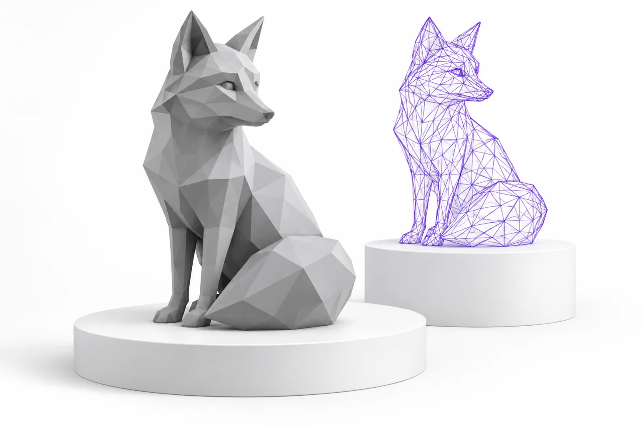
AI-generated editorial illustration, not a screenshot of a conversion result.
OBJ to STL conversion is a geometry handoff. It is useful when an application accepts OBJ but your next workflow expects STL, particularly for inspecting or slicing a triangle surface. The conversion can preserve the visible shape while leaving materials and textures behind. To get a dependable result, check which objects are included, what the coordinates mean and whether the source is a printable surface rather than a model designed only for rendering.
Identify the purpose of the OBJ file
OBJ appears in many workflows, from scanned objects to game assets and CAD exports. A model made for a rendered image may contain open surfaces, overlapping pieces or extremely thin details. Those can look convincing under lighting without defining a closed printable volume. Before converting, determine whether the file represents a solid object, a collection of surface patches or a scene assembled for visualization.
If the source was designed for printing and the next application requires STL, begin with the OBJ to STL converter. If the source was made for rendering, plan for a separate print-preparation step. Changing the file format does not add wall thickness, remove internal overlaps or decide which decorative details should become physical geometry.
Separate geometry from material resources
An OBJ commonly travels with an MTL file and texture images. Those resources influence appearance, while vertex and face records describe the mesh. A standard STL does not carry the same material or texture system. The local conversion focuses on polygon geometry, so an otherwise complete OBJ can produce a gray STL even when its source appeared colorful.
Keep the original package if you may need its appearance later. Do not delete the MTL and image files just because they are unnecessary for one geometry-only export. If a design feature exists only in a texture, such as a printed label or simulated surface pattern, it will not automatically become raised or recessed geometry in the STL. Model that detail explicitly or use an appropriate relief workflow.
Check whether surface detail is real geometry
Rendering applications can create apparent detail through normal maps, bump maps and other shading techniques. These change the way light interacts with the surface without necessarily changing the mesh boundary. A smooth object covered by a detailed texture can therefore export as a simple smooth shape. The converter has not removed a geometric feature if the feature was never represented by vertices and faces.
Displacement is a separate case and depends on whether it has been evaluated into the exported geometry. If your modeling application supports a modifier that changes the actual surface, apply or evaluate it through a deliberate export workflow. Check the resulting OBJ in an independent viewer before converting. This helps distinguish an export omission from a conversion problem.
Understand triangulation
OBJ can describe polygon faces with more than three vertices. STL consists of triangles, so those faces must be triangulated. On a flat, well-formed polygon this can preserve the intended surface closely. Nonplanar polygons are more ambiguous because different diagonals can define different surfaces. Self-intersecting polygons and malformed face definitions create further uncertainty.
For a critical model, triangulate in the source application where you can inspect and edit the result. Look at long thin faces, complex concave regions and areas that change shape when a diagonal is moved. Export the triangulated mesh and compare it with the original. Deliberate triangulation gives you control over a step that an automatic importer otherwise has to perform on your behalf.
Triangle count is not a quality score
A model with many triangles may contain redundant detail, noise or unnecessarily dense flat areas. A smaller model may represent a simple shape accurately. Evaluate the geometry that matters for the intended size and use. If simplification is needed, inspect the effect on holes, thin walls and curved silhouettes rather than choosing a target file size without looking at the surface.
Make scale explicit
OBJ and standard STL do not provide a universally dependable unit convention for every workflow. The local OBJ conversion preserves numeric source coordinates. A coordinate span of 20 remains approximately 20 in the exported mesh; whether the next application calls that millimeters, centimeters or another unit depends on its import settings.
Use a known reference dimension to establish the correct interpretation. A scanned object should have a measurement taken from the physical item or from a documented scan setup. A modeled part should have an intended dimension in the source project. Record that reference and verify it after import into the receiving application. Automatic camera fitting makes scale errors difficult to detect visually.
Review transforms before export
A modeling application may store object translation, rotation and scale separately from local mesh coordinates. Its OBJ exporter may apply those transforms, depending on export settings. Check the exported file rather than assuming that what you see in the application viewport is exactly what was written. Negative scales and mirrored objects deserve particular attention because orientation and face winding can be affected.
When possible, export a selected object in a simple, documented state. Apply transforms only when you understand their effect on the source project, and keep a copy before doing so. If a result is rotated unexpectedly, first check axis conventions. Orientation can be corrected for printing, but a scale error or mirrored feature should be resolved deliberately rather than hidden by a convenient viewing angle.
Know what happens to multiple objects
An OBJ can contain several named objects or groups. A single STL may contain their triangle surfaces together without preserving those names as an editable scene hierarchy. Several disconnected parts can therefore appear in one file. That is different from merging them into a continuous watertight solid.
If you need individual parts, export them separately or separate the mesh in a suitable editor before handoff. If you need one solid, use the appropriate modeling operations and inspect the boundaries afterward. Overlapping shells can create unexpected slicer behavior, especially when they have inconsistent winding or very small gaps. A successful format conversion does not decide how those shells should interact physically.
Use a controlled conversion sequence
Save the source package and select the OBJ file that corresponds to the intended revision. Convert it, then rotate the preview and check the displayed dimensions. Look for missing pieces, inverted regions and stray geometry far from the main object. Download the STL using a name that distinguishes it from the original OBJ rather than overwriting your only source copy.
Reopen the downloaded file in the STL viewer or the receiving application. Compare the bounds, number of visible pieces and important features with the source. This second inspection verifies the actual handoff artifact. It is particularly valuable when you have several similar exports in a download folder and could accidentally select an older version.
Inspect mesh integrity separately
Open edges, nonmanifold connections, self-intersections and duplicate faces are geometry issues. They may already exist in the OBJ. A converter that rewrites the surface as STL does not necessarily repair them. Use a mesh inspection tool or your slicer's diagnostics to identify the specific problem. Avoid assuming that a smooth shaded appearance proves that the model is closed.
Repair methods can change the intended form. Automatically filling a hole may close a deliberate opening, while removing an apparently isolated shell may delete a small but important component. Inspect the repair locally and compare it with the original. For extensive changes, consult the guide to editing STL files and choose an editing method appropriate to the kind of defect.
Prepare rendering assets for printing
A character, architectural visualization or game prop often needs additional work before printing. Hair strands, leaves, cloth and thin panels may be represented as surfaces with no useful thickness. Floating details may need supports or connections. Internal geometry that was harmless in a rendered scene can complicate slicing and waste material.
Decide which details should survive at the final physical size. Add thickness where needed, connect fragile elements appropriately and remove irrelevant scene objects. Then export and convert the revised geometry. This sequence is more reliable than expecting STL conversion to infer manufacturing intent from a visually attractive asset.
Investigate common errors systematically
If the converter reports that the OBJ contains no polygon faces, verify that the file is actually a surface mesh. A point cloud or a list of vertices alone is not enough to define the intended boundary. Reconstructing a surface from points is a separate operation with its own assumptions. Renaming the file or repeatedly choosing another output extension will not add missing faces.
If processing reaches a size or triangle limit, isolate the part you need or simplify the mesh in the source application. If only one object fails, export that object separately for inspection. A compact reproducible case makes it easier to locate malformed face indices, extreme coordinates or a problematic polygon. Keep conversion warnings together with the source revision and the settings used.
Document the handoff
When sharing the STL, state the intended units, a reference dimension and whether the file contains multiple disconnected pieces. Mention that textures and materials are not included. This lets the recipient distinguish an expected geometry-only export from an incomplete delivery. If the recipient needs UVs, material assignments or object organization, OBJ or another richer format may be the better handoff.
For the reverse direction, read the STL to OBJ guide. Converting back can provide an OBJ container for existing triangles, but it cannot reconstruct the texture coordinates and materials discarded earlier. Keep the original asset package as your editable reference and treat the STL as a purpose-specific output.
How to convert an OBJ file to STL without changing the intended size
Before converting an .obj file to STL, write down a known dimension. OBJ coordinates do not reliably tell the next application whether a value represents millimeters, centimeters or another convention. Export the mesh, import it with the intended unit interpretation and compare the recorded measurement.
Use the saved STL for the final check. The preview camera can normalize the apparent size on screen, so a visually similar object may still need a different import-unit setting. Correct a uniform scale error deliberately rather than estimating the size by eye.
Is an OBJ to STL online converter enough for this model?
For a clean surface mesh, format conversion may be the only handoff step needed. For open surfaces, intersecting shells or nonmanifold edges, use an editor that exposes the affected geometry and lets you compare repairs against the original.
You can convert OBJ to STL free of charge with the browser tool, but conversion is not evidence of printability. Check the first layer, thin walls and internal regions in the slicer before starting a print.
Convert OBJ file to STL · Understand which mesh repairs require editing