
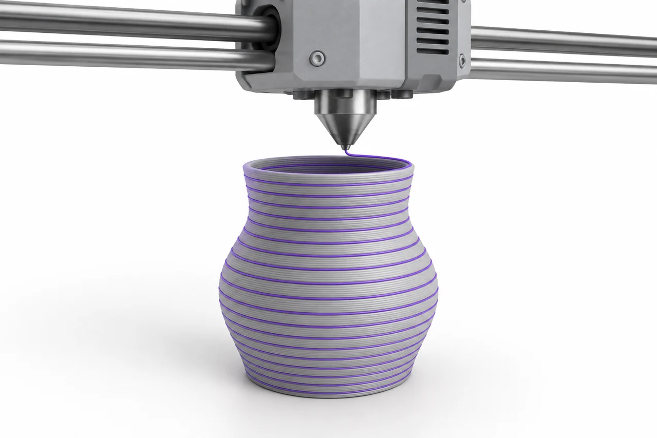
AI-generated editorial illustration, not a screenshot of a conversion result.
Converting STL to G-code means preparing a manufacturing job for a particular printer. The STL describes a triangular surface. G-code describes machine actions: where to move, how much material to extrude, and which operating settings to use. A slicer connects those two descriptions by dividing a model into layers and planning paths. Renaming a file cannot perform that work, and a G-code file made for another machine is not a reliable starting point.
Start by checking the mesh in the STL viewer. Then use a slicer configured for your printer, nozzle, material and build surface. STL File Maker helps create and inspect the mesh; it does not generate a printer-specific G-code program. This guide explains the decisions between downloading an STL and starting a print, including the checks that catch common errors before material is consumed.
Why a printer profile matters
A printer profile defines the machine that will execute the result. Bed dimensions, coordinate origin, maximum travel, extrusion system and supported command dialect all influence the generated instructions. Even two printers with similarly sized beds can require different start sequences or temperature handling. Select the exact supported printer profile when available. If you create a custom profile, work from the machine manufacturer's specifications and verify the resulting movements carefully.
The nozzle diameter is part of this configuration. It affects possible extrusion widths, practical layer heights and the visibility of narrow features. A logo designed around fine lines may look clear on screen but lose those lines when sliced for a larger nozzle. Changing a nozzle setting in software does not change the hardware, so keep the two consistent before interpreting the layer preview.
Store a known working profile separately from experiments. When a new result fails, comparing it with an established setup is much easier than reconstructing every setting from memory. A useful job record includes the printer profile, filament profile, nozzle size, slicer version and any intentional overrides. Those details belong with the slicing project, because a geometry-only STL does not contain them.
Confirm model size before choosing quality
STL does not provide a dependable standardized unit declaration. A coordinate distance of 20 can be interpreted differently by different import workflows. After importing, compare the displayed dimensions with a known measurement. A supposed 100 mm sign should not arrive as a tiny object or a model larger than the build plate. Correct the interpretation before adjusting layer height, supports or infill.
Use a consistent dimensional reference rather than guessing from the camera view. A hole diameter, overall width or mating edge can serve this purpose. If the source was CAD, compare against the original drawing or design. If the source was an image converted with PNG to STL, compare the slicer's width with the value chosen during conversion.
Scaling also changes practical feature size. Reducing a 100 mm sign to 30 mm shrinks every stem, gap and attachment bridge. A mesh can remain mathematically valid while becoming too delicate to print. Inspect the smallest important features after scaling. For lettering, our text-to-STL preparation guide explains why readability depends on physical strokes and spacing rather than resolution alone.
Choose an orientation that supports the design
Orientation changes the shape of each layer and the relationship between layer lines and applied loads. The largest flat face is often a convenient starting point, but it is not automatically best. Consider contact area, visible surfaces, overhangs, support removal and the direction of any mechanical stress. A decorative relief usually has a clear flat backing, while a bracket may require a more deliberate compromise.
Keep the object on the build surface unless your process explicitly requires another arrangement. An imported model can contain an offset origin or several disconnected pieces. Use the slicer's placement tools to inspect them rather than assuming that what looks centered in a 3D viewer is ready to print. Multiple bodies may need independent placement, or may be intended to remain in a precise assembly.
Watch for unsupported islands in the first few layers. A floating dot above a letter, a disconnected logo detail or a raised feature without material beneath it cannot begin in empty space. The solution may be a connecting bridge or backing in the model, a different orientation, or support material. The layer preview reveals this more clearly than a shaded exterior view.
Set layer height and wall structure together
Layer height controls vertical sampling. Smaller layers can improve sloped surfaces and fine height changes, but they increase the number of layers and usually the print time. They do not restore detail absent from the mesh. If a circle was exported with a visibly coarse polygon boundary, making layers thinner will not turn that boundary into a smooth CAD curve.
Walls establish the exterior shell. Their count and extrusion width affect strength, detail and the space available for infill. A narrow stroke may be filled entirely by wall paths, while a broad plate can contain many internal regions. Inspect how the slicer handles thin features rather than assuming that a particular wall count will fit every part of the design.
Top and bottom layers also deserve attention. A relief with a thin backing needs enough continuous material to support the raised surface. A large flat top over sparse infill may show the support pattern underneath. Adjust settings with the actual geometry in mind, and consider a small representative test if appearance or stiffness is important.
Understand infill without treating it as the whole structure
Infill occupies internal space that is not taken by walls or solid surface layers. More infill can change weight, stiffness and print time, but it is only one part of the structure. Wall layout, orientation, material and layer bonding can matter just as much. A decorative plaque and a loaded fixture should not automatically share the same assumptions.
Look at the sliced cross sections of the regions that matter. A very thin object may contain little or no conventional infill because its top and bottom layers overlap. A thick block can have a substantial internal pattern. Knowing which situation applies prevents you from changing an infill percentage that has almost no effect on the part you are evaluating.
For functional parts, test the actual use case rather than treating a slicer percentage as a certification. Our free STL examples are useful for basic dimensional and viewer checks, but a calibration cube does not validate the strength of a different geometry. Use a representative prototype and document the conditions of the test.
Plan supports and adhesion deliberately
Supports provide material beneath surfaces that the printer could not otherwise form reliably. They can also add cleanup work and leave marks on contact areas. Before enabling support everywhere, inspect whether rotating the model or modifying an overhang would provide a better result. A small design change can sometimes remove a large amount of unnecessary support.
Adhesion settings address the connection between the first layer and the build surface. A brim may help a narrow footprint, but it does not correct an unclean surface, an unsuitable temperature or an incorrectly calibrated first layer. Follow the material and machine guidance for preparation, then evaluate adhesion aids as part of that complete setup.
Check support interfaces and removal access. Material trapped in a deep enclosed cavity may be difficult or impossible to remove. The ability to generate toolpaths there does not make the final object useful. Where an opening must remain clear, examine its actual sliced layers and consider whether the model needs to be split or redesigned.
Read the layer preview before exporting
The layer preview is the most useful checkpoint between a mesh and a machine job. Move from the first layer to the last and look for missing walls, unexpected gaps, isolated regions and sudden changes in cross section. Compare visible toolpaths with the intended form. A shaded preview of the mesh alone cannot show every slicing decision.
Inspect narrow letters, thin rims, holes and the roof of any cavity. If a feature disappears, determine whether it is too small for the configured extrusion width or whether the mesh contains an error. A repair operation may help a broken surface, but it cannot make an intentionally tiny feature physically wider without changing the design.
Review the estimated material and duration as a reasonableness check. A small token estimated to consume a large spool suggests a scale or configuration problem. Estimates are not exact promises, but large surprises are worth investigating before export. Save the slicing project so that the decisions remain editable after the G-code has been written.
Keep the source mesh and project alongside G-code
Give each output a clear name that identifies the model and the intended machine setup. Keep the source STL, the editable design if available, and the slicer project in the same organized workflow. G-code is an output artifact, not a substitute for those sources. Recovering a clean model from paths later can be incomplete, as explained in our G-code-to-STL guide.
If you share a design, sharing geometry is usually more portable than sharing a prepared machine job. A recipient can slice the model with their own printer and material profile. If you also provide settings, describe them as your tested conditions rather than universal requirements. Different hardware, filament and firmware can require different choices.
A successful STL-to-G-code workflow therefore has several distinct checks: correct geometry, correct dimensions, suitable orientation, appropriate process settings and a sensible layer preview. Complete them in that order. When the preview disagrees with the design, fix the cause before starting the print. That habit saves more time than repeatedly printing a flawed setup and hoping that one small setting will compensate for everything else.
Prepare an STL for your MakerBot printer
An STL GCODE workflow must target a real printer profile. A generic mesh converter cannot choose the correct machine instructions for every MakerBot printer. Use compatible slicing software for the exact printer and its required output, then inspect the layer preview and settings before printing. This site does not provide a direct printer-instruction or MakerBot output generator.
Check the STL geometry first · Understand why reversing toolpaths is difficult