
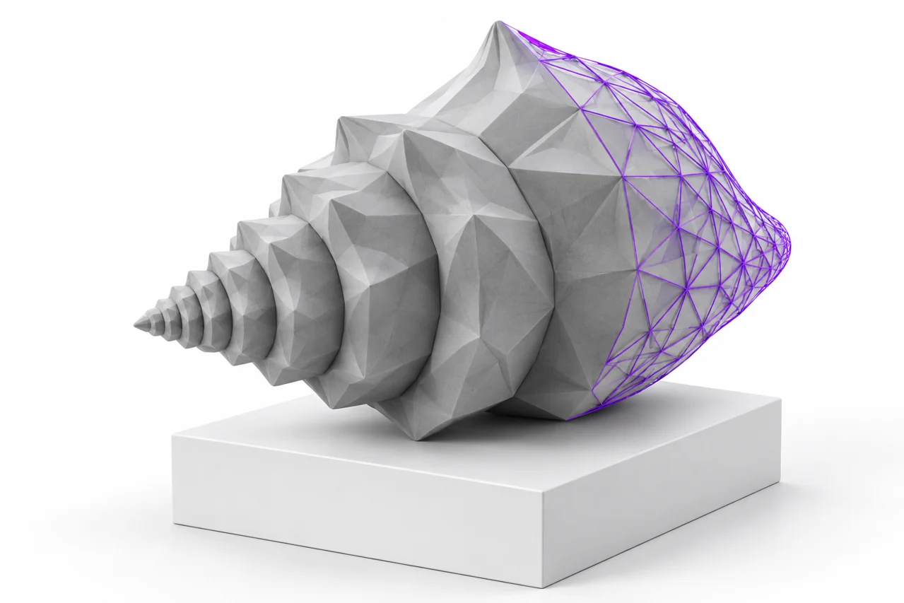
AI-generated editorial illustration, not a screenshot of a conversion result.
Converting STL to OBJ can make a model easier to import into a mesh-editing or visualization workflow. The conversion changes how the geometry is written, but it does not restore information that STL never stored. The result remains a triangle mesh. Materials, texture coordinates, object names and the original modeling history do not appear simply because the destination format can support some of them.
Use the STL-to-OBJ converter when you need a geometry-only OBJ from a binary or ASCII STL. The tool retains numeric coordinate values and writes vertices and faces. This guide explains how to preserve scale, understand shading differences, prepare the mesh for editing and check the exported file before treating it as a reliable part of a larger project.
Understand the information in the source
An STL describes triangles using vertex coordinates and normal-related data. Common binary and ASCII representations organize that information differently, but both are primarily surface geometry formats. They do not provide a dependable standardized scene hierarchy, texture map layout or universal unit declaration. Some software uses nonstandard extensions, which should not be assumed portable.
OBJ can represent vertices, polygon faces, texture coordinates and references to materials. A destination format's capabilities are not evidence that a conversion has populated all those fields. When the source is STL, the dependable transferable content is the surface geometry. A simple exported OBJ can be entirely useful while containing no material library or UV coordinates.
Set expectations before import. If your goal is to paint a texture, you will still need to create a suitable UV layout or use an editor's painting workflow. If your goal is parametric CAD editing, changing to OBJ does not create sketches or dimensional features. Read the mesh-to-CAD guide before choosing a format based only on its name.
Preserve scale with an explicit reference
The converter retains coordinate values. A distance of 20 in the source remains 20 in the exported geometry. The physical interpretation of that distance depends on the importing application. If one application assumes millimeters and another assumes meters, the same numeric coordinates can produce a major apparent size difference without any vertices being lost.
Record one or more known measurements before conversion. Overall width is useful, but a hole diameter or mating feature can provide a more specific check. After importing the OBJ, compare the displayed measurement with the intended physical size. Correct the import scale or unit interpretation deliberately rather than dragging the model until it looks plausible beside another object.
Be cautious about automatic normalization. Some viewers fit every object into the same camera frame, which can hide scale differences. Others resize imported models for presentation. A visually similar screenshot is therefore not sufficient evidence of dimensional preservation. Use measurements in an application that exposes actual coordinate or physical dimensions.
Expect triangles rather than a recovered modeling topology
An STL has already been tessellated. Curved surfaces are represented by flat triangles, and the export may not preserve the original polygon layout of a mesh editor. An OBJ written from that STL will normally reflect this triangulated structure. It will not reconstruct the artist's original quads, edge loops or subdivision cage.
Triangle geometry can be perfectly suitable for printing, scanning and visualization. It can be less convenient for certain deformation or subdivision workflows. If you need clean animation topology, plan a retopology step in the destination application. Automatic conversion is not a substitute for deciding where edges should flow around a joint or a detailed facial feature.
Do not judge success by a lower face count alone. Aggressive simplification can change a silhouette, close small gaps or distort a fit. Conversely, a large face count can preserve unnecessary noise. Evaluate the representation against the actual purpose of the model and preserve a copy of the unmodified conversion before making further changes.
Distinguish shared vertices from unchanged surfaces
STL commonly repeats vertex coordinates for adjacent triangles. An OBJ exporter may write those coordinates separately or combine exactly matching positions into shared vertex entries. Either representation can describe the same visible surface. File size and vertex count may change even when the triangle positions and shape remain equivalent.
Welding nearby vertices is a different operation from combining exactly equal coordinates. A distance-based weld can close small gaps, but it can also merge edges that were intentionally separate. Thin walls and closely spaced components are particularly sensitive. Choose a weld tolerance only after understanding the model's scale and inspecting the affected regions.
Shared coordinates do not guarantee a valid solid. Faces can still overlap, point in inconsistent directions or form nonmanifold connections. If the editing workflow requires a clean continuous surface, run appropriate topology checks in the mesh application. A successful file conversion means the geometry was represented, not that every possible structural defect was repaired.
Understand shading changes after import
The OBJ may look smoother or more faceted in the destination than the STL did in a previous viewer. This can result from normal calculation and shading settings rather than a change in the actual vertex positions. Smooth shading blends lighting across faces; flat shading shows each triangle's orientation more distinctly.
Inspect the silhouette and wireframe to distinguish appearance from geometry. A smoothly shaded low-resolution cylinder still has a polygonal boundary. Conversely, a finely tessellated surface can look harsh under flat shading while preserving its shape accurately. Adjusting display normals can improve presentation without changing the exported mesh.
If faces appear missing from one side, check face orientation and backface-culling settings. A viewer that renders both sides can hide inconsistent winding that becomes obvious elsewhere. Do not solve every visibility issue by duplicating or thickening surfaces. Diagnose whether the cause is display behavior, reversed faces or a genuinely open mesh.
Prepare for materials and textures separately
Assigning a material in the editor can change the rendered color or surface appearance. That is a new editing step, not recovered STL metadata. If you export an OBJ with a material library afterward, keep the associated files organized. An OBJ that references a missing material or image can load with default colors in another application.
Texture mapping usually requires UV coordinates that connect points on the mesh to positions in an image. An STL-to-OBJ conversion does not know how the original object should be unwrapped. Choose an appropriate UV workflow for the shape and intended texture, then inspect seams, stretching and resolution in the destination.
For geometry-only exchange, you may not need any of those assets. A plain OBJ with vertices and faces can be the simplest useful result. Keep the workflow focused on the intended use rather than adding texture files just because the format supports them. Document whether your delivered object is geometry-only or includes a complete material setup.
Edit the converted mesh with a clear objective
Typical mesh edits include cutting a base, removing an unwanted fragment, changing orientation or adding a new geometric feature. Work on a copy and save the application's native project format. That project can preserve separate objects and editable modifiers that a final OBJ or STL export may flatten.
For local dimensional changes, use measurements and suitable cutting or construction geometry. Stretching the entire object to enlarge one hole can distort unrelated features. Our STL editing guide explains how to choose between a direct mesh operation and reconstructing a dimension-driven CAD feature.
Inspect the result after each significant operation. A Boolean union can leave internal surfaces, and a cleanup operation can close an intended opening. Comparing with the original conversion helps identify the source of a new defect. Keep a short record of changes when the model will be handed to someone else for further editing.
Check the exported OBJ independently
Reopen the downloaded OBJ in the application you plan to use. Confirm the dimensions, orientation and completeness of the object. Look for detached components and examine important openings. A correct-looking front view does not reveal every issue, especially when several surfaces overlap or a feature is hidden on the underside.
If the final destination is printing, you can return supported geometry through OBJ to STL after editing. Read the OBJ-to-STL guide to understand the loss of material and texture information on that return path. Check sliced layers before manufacturing rather than relying solely on the converter's preview.
Keep the original STL, the first OBJ conversion and the edited project until the workflow is complete. Those checkpoints let you separate conversion issues from later editing changes. STL-to-OBJ is a useful bridge when you treat it as a geometry transfer with explicit scale checks. It becomes confusing only when the format change is mistaken for automatic repair, texture recovery or reconstruction of the original design process.
Use a known example to verify your import setup
If scale or orientation remains confusing, download the 20 mm cube from the free model library, convert it and import it using the same settings. Its known dimensions make an unintended scale factor easier to identify. This checks your import path, but it does not prove that an unrelated source file uses millimeters. Establish that second fact from the source design or a known measurement.
How to convert .stl to .obj and check the saved file
Open the converter with the original STL and select OBJ output. After conversion, compare the visible shells with the original model, download the export and load that downloaded file into your mesh editor. This checks the delivered file rather than only the converter preview.
If you convert an STL file to OBJ before editing, save a native editor project as well. That working project can preserve separate objects, modifiers and later changes that a simple geometry exchange file does not.
Convert STL to OBJ online on Mac or another device
The web converter uses the browser rather than a separate operating-system installer. Practical limits depend on browser support, memory and model complexity. Try a small representative mesh first and keep the original STL available if the device cannot process the full model.
There is no STL to OBJ converter download to install from this site. Download the converted model after checking its dimensions, then use an application suited to the edits you actually need.