
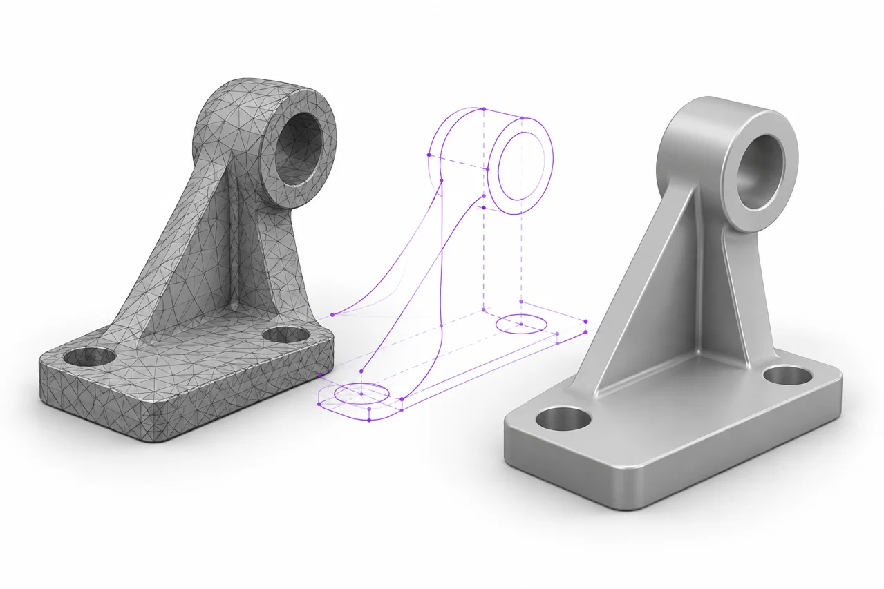
AI-generated editorial illustration, not a screenshot of a conversion result.
STL to STEP is often described as a simple file conversion, but it can mean several very different things. You might want a CAD application to accept an existing mesh, or you might need editable cylinders, planes and design features. Those goals require different amounts of work. Understanding the distinction helps you avoid a STEP file that opens successfully but is far less useful than you expected.
Define the outcome before choosing a method
Ask what the receiving person or application needs to do. Viewing a mesh inside a CAD environment is different from changing the diameter of a modeled hole. A faceted STEP representation may be sufficient for a reference shape or assembly context. A manufacturing change often benefits from reconstructed analytic geometry or, better still, the original CAD model.
If the original designer can provide a STEP export, request that file before attempting reverse conversion. The original CAD source may preserve surfaces and relationships that an STL has already approximated with triangles. Avoid spending hours reconstructing a shape when a suitable export exists. Keep the STL as a reference and confirm that any supplied CAD file represents the same revision.
What an STL actually gives you
An STL describes a triangle surface. It does not ordinarily include the sketches, constraints, feature tree or analytic definitions that produced that surface. A round hole is represented by facets, and a fillet is represented by a collection of flat triangles. Even a very fine mesh is still an approximation whose original design decisions are not directly recorded.
This is why changing the filename from .stl to .step does not work. A new file structure must be written, and a choice must be made about what geometry to represent inside it. It is also why a successful conversion cannot be assumed to restore exact design intent. A converter can only use information present in the source or infer additional structure through an explicit reconstruction process.
Faceted representation versus CAD reconstruction
One approach represents mesh facets as faces inside a CAD-compatible structure. The result may use the STEP container while retaining a large number of small planar faces. This can be useful for certain handoffs, but it does not transform a faceted cylinder into an exact cylinder or recover the original radius of a blended edge.
A reconstruction workflow goes further. It identifies or creates suitable planes, cylinders, freeform surfaces and other geometry, then establishes their relationships. That may involve fitting surfaces to the mesh, manually rebuilding features or combining automated tools with engineering judgment. The process can produce a more useful model, but it also introduces choices and approximations that should be documented.
A changed extension is not evidence of editability
Open the result in the receiving CAD application and inspect how it is represented. Can you select a meaningful cylindrical surface, or do you see hundreds of tiny planar faces? Can you perform the intended operation reliably? A filename ending in .step answers a packaging question. It does not establish that the model has the editable structure required for your next task.
Check the mesh before attempting reconstruction
Inspect the STL for open boundaries, nonmanifold connections, duplicate surfaces and stray components. These issues can make downstream operations difficult. A closed, consistently oriented mesh is generally a clearer starting point than a damaged surface, but repairing it should preserve the intended form. Automatically filling every opening can remove deliberate holes or vents.
Use the STL viewer for an initial inspection and a mesh-analysis tool for topology diagnostics. If you need to repair or separate the source, read the STL editing guide. Save the original before modifying it so that you can compare repairs and avoid losing the only record of the supplied geometry.
Establish scale with a known dimension
Standard STL does not provide a dependable unit field. Before fitting surfaces or rebuilding features, establish what its numeric coordinates mean. Use a dimension from a drawing, a known physical measurement or information supplied by the original author. A uniformly wrong scale can make every fitted radius and reconstructed feature wrong at once.
Do not infer units from how large the model appears in the viewport. Most applications fit the object automatically. Record the chosen unit convention in the CAD document and confirm a second independent dimension when possible. If the STL came from a scan, distinguish the precision of the scan from the precision implied by displaying many decimal places.
Choose detail according to the job
A highly dense mesh can be difficult to manipulate if each facet becomes a separate face. Simplification may make a reference conversion more practical. However, reducing the mesh before reconstruction can also remove useful information about small features. Decide which surfaces and interfaces are important before choosing a reduction target.
For a mechanical bracket, mounting-hole positions and contact planes may matter more than decorative surface texture. For an organic sculpture, the overall silhouette and broad curvature may matter more than converting every local detail into a CAD feature. The appropriate representation depends on the next operation, not on an abstract goal of producing the largest possible file.
A workflow for simple mechanical parts
For a part dominated by planes, holes and simple profiles, manual remodeling can be more useful than retaining every triangle. Import the mesh as a reference, align it to a sensible coordinate system and identify the principal dimensions. Build sketches and features that express the intended design, then compare them with the reference mesh.
Do not blindly fit every irregularity. Small deviations may result from tessellation, scanning noise or an earlier repair. Where a drawing or known design requirement exists, use it to guide the reconstruction. Where you are inferring a dimension from the mesh alone, record that uncertainty. A clean-looking CAD model should not imply a level of certainty that the source cannot support.
A workflow for freeform or scanned shapes
Organic surfaces and scans can require a different approach. There may be no simple set of extrusions and cylinders that captures the shape efficiently. Surface fitting or specialized reverse-engineering tools can help, but they require choices about smoothness, tolerances and patch structure. A mesh may remain the most appropriate representation for some tasks.
If the receiving workflow accepts a mesh, ask whether STEP is truly necessary. Converting a detailed organic model into a cumbersome faceted CAD structure may make it harder to work with without adding useful editability. When STEP is required, test a representative region or simplified version before committing to a large reconstruction effort.
Validate against the source, not only the new model
Once you have a candidate CAD representation, compare it with the original mesh. Check overall dimensions, hole locations, contact surfaces and any feature that motivated the conversion. A deviation analysis can be useful when available, but its results need interpretation. Small distance values do not automatically prove that the reconstructed topology or feature structure is appropriate.
Also test the intended downstream operation. If the goal is to enlarge a hole, perform that edit on a copy. If the goal is assembly placement, verify mating references and clearances. If the goal is manufacturing handoff, ask what geometry representation and tolerances the recipient actually requires. Validation should be tied to the reason for creating the STEP file.
Recognize common warning signs
A very large STEP file with thousands of tiny faces often indicates a faceted representation rather than meaningful reconstruction. Slow face selection or failed Boolean operations may follow. This does not necessarily mean the file is corrupt, but it may mean that the chosen method does not suit the intended edit.
Another warning sign is a model that looks smoother but no longer matches important dimensions. Aggressive fitting or simplification can improve appearance while moving interfaces. Compare specific measurements and inspect sharp transitions. If the result requires extensive repair after every operation, reconsider whether a simpler remodeled part or the original CAD source would be a better foundation.
Keep forward and reverse conversion expectations separate
Converting STEP to STL tessellates available CAD geometry. Reconstructing CAD from STL attempts to create structure from an already tessellated surface. Those are not symmetrical operations. A round trip through STL can discard information that cannot be recovered exactly, even when both file conversions complete without errors.
Read the STEP to STL guide to understand the forward tessellation settings. If you already have a valid STEP model and need a printable mesh, use the STEP converter. If you only have STL, choose a reconstruction or reference-import workflow based on the edit you actually need rather than assuming the reverse conversion restores the original design.
Document what the result represents
When handing off a reconstructed or faceted STEP file, describe the method used. State whether it contains fitted analytic geometry, manually remodeled features or a faceted representation of the source mesh. Include units, reference dimensions and any important assumptions. This helps the recipient assess what can be edited reliably and what still requires verification.
Keep the original STL, an intermediate working document and the exported STEP separately. Record the source revision and significant reconstruction decisions. A transparent handoff is more useful than calling every converted file fully editable CAD. The best result is the representation that supports the intended work while making its limits understandable.
An STL STEP converter cannot recover design history
A triangle mesh does not record the original sketches, dimensions or modeling operations. Software may construct a faceted CAD representation or help rebuild surfaces, but changing the file extension alone does not make the design parametric. There is no automatic STL-to-STEP tool on this site.
3MF to STEP has the same geometry question
If the useful content of a 3MF model is a triangle mesh, extracting that mesh does not recreate the original analytic CAD surfaces. Treat 3MF to STEP as a separate external reconstruction workflow, preserve the source model and compare both shape and dimensions after rebuilding.
Inspect supported 3MF mesh geometry · Choose mesh editing or CAD reconstruction