
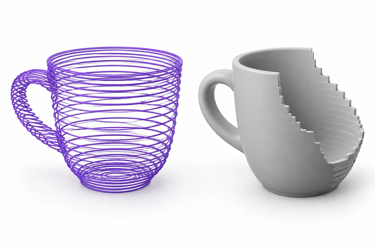
AI-generated editorial illustration, not a screenshot of a conversion result.
A G-code file can look like a model when opened in a toolpath viewer, but it is not the original model. It records instructions produced for a manufacturing process. In a typical filament-printing workflow, those instructions describe travel, extrusion, temperatures and related machine actions. The STL that existed before slicing described a surface. Converting back therefore requires interpretation, and some information has already been discarded.
If your goal is to recover a lost design, first search for the source STL, an editable CAD document or a saved slicer project. Those are better starting points than reconstructing toolpaths. This guide explains what a G-code-to-STL workflow may recover, what it cannot reliably infer, and how to assess a reconstruction. STL File Maker does not offer a one-click promise to restore an original solid from arbitrary printer instructions.
Toolpaths and surfaces answer different questions
A surface mesh answers a geometric question: where is the boundary of the object? A toolpath answers a process question: where should a machine move while making it? A slicer may create several wall lines inside a boundary, sparse infill within it, solid layers near a top surface, and support structures outside it. Those paths are related to the intended object, but they are not a direct copy of its exterior.
Travel moves make the distinction especially visible. A nozzle can move across empty space without depositing material. A reconstruction that connects every movement into geometry will add lines that never belonged to the object. Extrusion amounts help distinguish deposition from travel, but retractions, relative positioning and firmware-specific behavior complicate that interpretation.
Other manufacturing processes create additional ambiguity. Milling, laser cutting and filament printing can all use G-code-like instructions, yet the meaning of the physical result differs. A toolpath intended to remove material cannot be interpreted as though it deposits a plastic bead. Identify the source process and machine context before selecting any reconstruction method.
Look for a better source before reconstructing
Check the download folder, design application, project archive and any cloud storage used during the original workflow. A slicer project may contain the mesh as well as process settings. A 3MF file can be a useful lead, although its exact contents depend on the application that created it. Do not assume that every 3MF is only a printable model or that every project is a simple core 3MF package.
If you find a supported model package, try the 3MF-to-STL converter and inspect the result. It reads supported build geometry and applies placement, but it does not preserve all application-specific project settings. Our 3MF conversion guide explains the distinction between geometry, components and additional metadata.
Search by model name and approximate date rather than only by the final G-code filename. Slicers sometimes append profile names, timings or other information during export. A renamed machine file may have little resemblance to the original design filename. If another person supplied the job, requesting the source geometry can save much more time than reverse engineering it.
Read the coordinate and extrusion modes
A G-code interpreter needs state. Position values can be absolute or relative, and extrusion can follow a separate mode. Commands can reset the current coordinate value without physically moving the machine. Ignoring those changes can produce stretched paths, giant jumps or material in the wrong place. A plain text parser that extracts every X, Y and Z number is not enough.
Arcs introduce another question. Some files use arc commands instead of many straight segments. A compatible interpreter must understand their plane, endpoint and center conventions and sample them with an appropriate tolerance. Unsupported motion commands can create missing or incorrectly shaped portions of the reconstruction even when most of the preview looks plausible.
Comments may identify layers, extrusion width or feature types, but those comments are not universal. A file from one slicer can use different labels from another, and post-processing can remove them. Treat comments as helpful context rather than a guaranteed specification. Record the slicer and profile when known, because they help explain the assumptions behind the paths.
Choose whether you need a path display or a solid approximation
A path display draws lines that show where the nozzle traveled. It is useful for examining a job and finding missing regions, but it does not necessarily create a closed volume. Exporting those lines to another format can still leave you with a point or curve representation that a slicer cannot treat as a printable solid.
A solid approximation gives deposited paths a width and height. The method may sweep a bead-shaped cross section along each extrusion move, then combine overlapping volumes. Its result depends on assumptions about layer height, bead shape and actual extrusion. Those assumptions may be useful for visualization, but they do not recreate the exact surface that existed before slicing.
The difference matters when choosing a destination. For an illustration of nozzle motion, a line representation may be sufficient. For a rough mock-up, a bead volume might be useful. For a precisely fitting replacement part, reconstructing the design from measurements is often more appropriate than treating a path-derived surface as an authoritative model.
Separate the object from supports and auxiliary paths
A printing job can include a skirt, brim, raft, purge structure or support material. These are intentionally generated manufacturing aids, not necessarily part of the desired object. A path-to-volume conversion may include all of them unless it understands reliable feature labels or you remove them manually afterward.
Supports are particularly difficult because they can sit very close to or beneath the object. Their paths may be separated by a small gap that is meaningful to printing but hard to interpret in a simplified volume. Automatic merging can attach supports to the recovered object, while an aggressive separation operation can remove legitimate thin features.
Inspect the reconstruction in sections and compare it with the original toolpath preview. Identify which regions are intended geometry and which are process aids. Keep the unedited reconstruction as a reference before deleting anything. If the file contains multiple objects, work on one at a time and verify that shared purge or support structures are not being mistaken for model components.
Expect layered surfaces and missing interior information
A recovered object often carries the layer structure of the printing process. Its outer wall may look like stacked beads rather than a smooth design surface. Smoothing can reduce that appearance, but it can also change dimensions and erase small details. The result becomes an interpretation of the print process rather than a faithful return to the source design.
Internal information is incomplete in a different way. Sparse infill does not define every point in the original solid. Several original shapes could lead to similar paths under a particular slicing setup. Areas that were not printed because they were too small or invalid cannot simply be recovered from the machine file.
A feature that disappeared during slicing is therefore not available for a later converter to restore reliably. Compare any reconstruction with drawings, photographs or measurements if the original function matters. Where a cavity, hole or mating surface has a critical size, rebuild and verify that feature explicitly rather than assuming it survived the conversion.
Inspect the mesh before using it again
If the reconstruction produces STL, open it in the STL viewer to check overall shape and dimensions. Then inspect it in a mesh-editing application that can identify open boundaries, self-intersections and disconnected shells. A visible object is not necessarily a valid closed mesh, and a large triangle count does not prove geometric quality.
Check for accidental bridges where travel paths were interpreted as deposition. Look for thin strings across holes, tall spikes from coordinate resets and detached fragments near the print area. These patterns often indicate parser assumptions rather than defects in the original design. Fix the interpretation when possible instead of trying to sculpt away every symptom.
Use the STL editing guide to choose a repair or remodeling workflow. If you need to move the mesh into another editor, STL to OBJ can change the file representation. That conversion does not repair the geometry or restore missing design information; the same structural issues remain until you address them.
Prevent the same recovery problem next time
Keep three separate kinds of source: the editable design, the exported mesh and the slicing project. Each serves a different purpose. The design preserves modeling intent, the mesh supports exchange, and the project records the manufacturing setup. Save the final G-code as an additional output associated with a particular printer and material, rather than as the only surviving file.
Use names and folders that make the relationship clear. Include a revision identifier when the geometry changes and another when only slicing settings change. A short note explaining the intended dimensions, material and orientation can prevent confusion months later. Back up the source files before deleting old working folders or resetting a computer.
G-code reconstruction can still be useful for investigation, visualization and approximate recovery when nothing better exists. Its value comes from understanding its limitations. Define what you need to recover, identify the original process, validate the interpreter and inspect the resulting geometry. For future jobs, follow the STL-to-G-code workflow while keeping the original sources, so that the manufacturing output never becomes the only copy of the design.
GCODE to STL recovery starts with the source model
Look for the original STL, 3MF model or saved slicer project before trying to rebuild a surface from movement instructions. G-code can include supports, travel moves and other printer-specific paths, so a visible toolpath is not a faithful original solid. No direct G-code converter is provided on this site.
Understand the forward slicing workflow · Check supported input formats